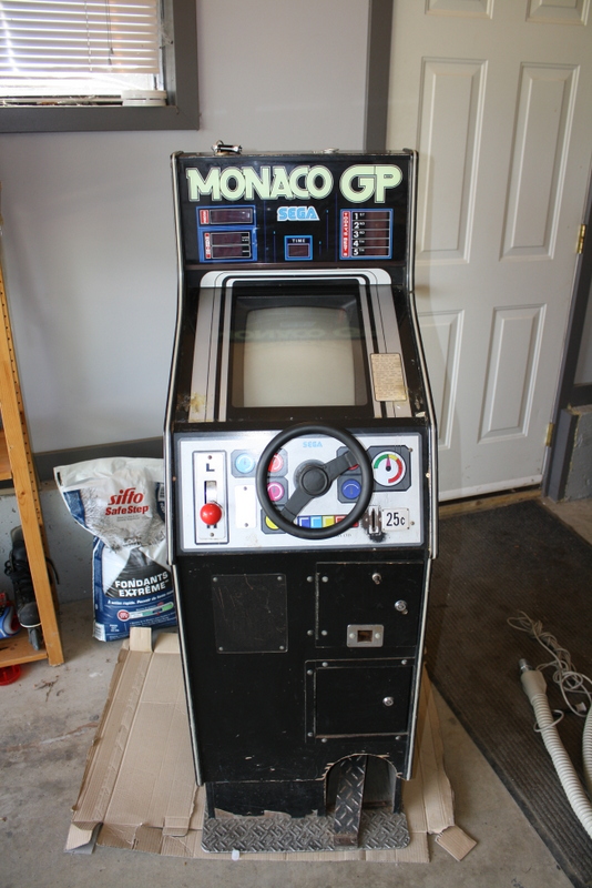
Monaco GP Questions

Sirjess

Newbie
Credits
8CR
Hello,

I while ago I finaly saw a Monaco GP stand up for sale here in Saskatchewan, I have wanted one for a decade but NEVER see them for sale anywhere close. I bought the machine knowing there was a few problems and hopeing I could fix them. There is a sound issue (only beeping sounds) and a time left problem (skips 40 seconds).

But first lets start with some easier stuff.

This machine is scary full of wires and components inside.
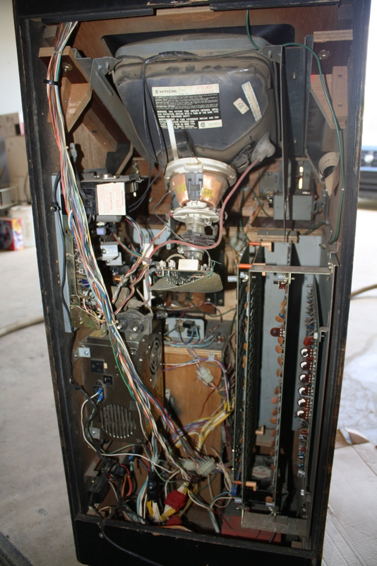
IMG_6671.JPG


Question 1, Is that a non original power supply on the left? Here is a close up.
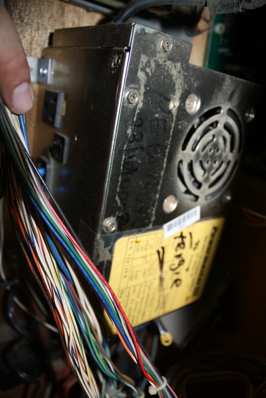
IMG_6669.JPG


I ask only because I can not find a good picture online of this Cab at all, and it will make tracing wires a bit different.

Also as I was cleaning the boards I found a broken Capacitor, should I just replace it with another 100nF cap though I am not sure on the wattage. I dont have much electronics experience so any help would be appreciated.

2013-07-17_14.47.15.jpg


Thank you for the help.

p.s. I did post these same questions on a different Arcade site, and one of the nice members directed me here because he said a few people own this same machine.
 

guddler

Busting vectors like it's 1982!
vacBacker
Feedback
10 (100%)
Credits
4,058CR
No, that PSU is not original. But if it works, it works - I'd leave it. The original would be in the base of the cab under the PCB stack.

Don't worry about replacing that cap. It's only a filter cap and won't be contributing to your problems.
 

guddler

Busting vectors like it's 1982!
vacBacker
Feedback
10 (100%)
Credits
4,058CR
Actually, before making sweeping statements like the PSU isn't original, can we see a picture of the front of the machine please just to be sure this isn't some obscure licensed version and that it is a genuine Sega? I say that because the monitor chassis is not in the normal place either, though I can't remember if it looks like the original chassis or not as mine was missing.

Also, where your monitor chassis is, you should have the LED display driver board and strangely I don't see it in there at all...
 

Sirjess

Newbie
Credits
8CR
It is an original as far as I know.

IMG_6664.JPG


The stearing wheel has been repaired and painted so I need to figure out how to make it look more original. But before I restore it I want to make sure I can get it working properly.

I think I would like to replace that Capacitor just to make sure, do you know what I would have to ask for, and is there any problems replacing it could cause?

Here is a link to the manual if anyone is interested. http://arcarc.xmission.com/PDF_Arcade_Manuals_and_Schematics/Monaco_GP_Stand_Model_(420-0445).pdf
 

guddler

Busting vectors like it's 1982!
vacBacker
Feedback
10 (100%)
Credits
4,058CR
Do your LED displays work? I'm curious as to where the board for them is!

That cap is really, really not going to make any difference. As to whether it will cause any problems, no, not provided you don't mess it up or short anything out doing it
smiley36.gif
I would imagine any typical value cap will do the job, like a 0.1pf Ceramic disc capacitor.
 

trm

Who loves you, and who do you love?
Feedback
2 (100%)
Credits
2,877CR
Hi Sirjess,

That is a nice cab - I've always wanted one of them. Not necessarily for the game but because they're one of few games that doesn't have a CPU and is built entirely out of logic chips.

I would really avoid doing any unnecessary work on the PCBs though as it'd be a nightmare to troubleshoot and fix if anything goes wrong. That's the downside of the way they've designed the hardware using pure logic. Each part of it can be almost working, but not quite working properly or failing utterly whereas you tend to see more distinct problems with a CPU based design.

That cap is used to provide a tiny reservoir of current so that when the chip switches between on/off, the cap can balance out the tiny drop in voltage. But because almost every chip has one wired to it, the loss of one won't make any difference at all. It's a risk-reward thing because that split cap won't cause you any problems but removing the board, doing the soldering and getting it back in might cause real problems.

If you do decide to replace it, you just need a basic decoupling cap as Gudd mentioned. No specified wattage, just a low value ceramic disk. Pretty much any of these would do, you don't need high voltage ones as it's going on the 5V line.

http://www.ebay.ca/sch/i.html?_trksid=p2050601.m570.l1311.R6.TR7.TRC1.A0.Xceramic+dis&_nkw=ceramic+disc+104&_sacat=0&_from=R40

I know Gudd had/has? one of these and has probably spent quite a few hours working on its innards
smiley4.gif


cheers

tim

ps But I really wouldn't bother replacing it either :)
 

guddler

Busting vectors like it's 1982!
vacBacker
Feedback
10 (100%)
Credits
4,058CR
Glad it's not just me then
smiley36.gif


Yeah, still got it - there was an outcry when I suggested selling it so I bowed to peer pressure and just left it in the corner. Sadly, this is what happens when they go wrong. It isn't JUST because they're purely logic chip based, however as you say, that's problem enough! The bonus to that is that they tend to soldier on forever with multiple faults that are pretty minor and you don't really notice. Only when it get's to something that impacts you do you notice. Like mine. Won't coin up, and I assure you it's not the coin mechs!!

The MAJOR, MAJOR problem with these is that as you can see from the first pics, not only are the PCBs huge, they're also plugged into a cage. Unlike a lot of PCB cages the backplane that connects the three PCBs isn't a straight aligned bus type connection so it's impossible to plug the bottom board into the top and vice-versa. Sooo, as I'm sure you will have guessed by now, troubleshooting these is impossible. If the fault is known to be on the top board then you're fine, but if you know the fault is on the bottom board of the cage you're screwed as you can't get to it. The top board is in the way! And that's if you know where the fault actually is!

I've pulled mine out and randomnly checked some ICs related to coin up detection a couple of times but it hasn't ever fixed it. I've got a spare loom and backplane that Ade kindly gave me years ago. One of these days I'll remove the connectors from the backplane and make up a loom for the bench but it will be HUGE and take a VERY long time to do (did I also mention it would be tedious as well!).

Oh, and then you've got the terrible poor quality, hand drawn Japanese schematics to contend with
smiley36.gif


All in all, it's not a big surprise I've never heard of anyone actually fixing one of these unless they just replaced the PCBs
smiley5.gif


Good luck though and all that - don't let my doom and gloom stop you
smiley4.gif


I actually feel like having another crack at mine now. Or at least switching it on and swearing at it a lot. I'll take some pictures of the insides while I'm at it. I'm sure the one here is missing some stuff. I would also dearly like to know how to get to the fan that sits behind the displays. Mines really noisy and I'd like to replace it, but I've never been able to work out how to get to it.

Cheers!
 

ZedEx48K

8-Bit
Feedback
2 (100%)
Credits
1,422CR
trm said:
Hi Sirjess,

That cap is used to provide a tiny reservoir of current so that when the chip switches between on/off, the cap can balance out the tiny drop in voltage. But because almost every chip has one wired to it, the loss of one won't make any difference at all. It's a risk-reward thing because that split cap won't cause you any problems but removing the board, doing the soldering and getting it back in might cause real problems.

Could the cap not just be snipped in place at the top of the legs and a new one soldered to them?
 

Sirjess

Newbie
Credits
8CR
Ok thanks for the pointers about leaving the Cap, I might as well not worry about it then. So are you thinking that finding a solution to these problems is almost imposible? And I also can not understand the schematics so dont even know what chips to look at in regard to the problems I have.

Yes the LED displays work fine, the only problems are the sound and the skipping time, I will look at it this weekend and find where the LED board is.
 

guddler

Busting vectors like it's 1982!
vacBacker
Feedback
10 (100%)
Credits
4,058CR
Well, let's just say that if you're not well versed in PCB repair then you picked one hell of a cab decide to really want
smiley36.gif
I can understand though, it's a great little game.

I've got to go out during the day tomorrow, but hopefully at some point over the weekend I'll dig mine out so I can get to it. Maybe we can work out where to look and talk you through some debugging. I don't anticipate it being overly easy though!

Stick with it for the moment and let's see if we can help you. You never know, I might get mine working along the ride as well.

[EDIT] PS: Anyone else with experience on these machines care to chip in???

guddler2013-07-20 01:43:07
 

trm

Who loves you, and who do you love?
Feedback
2 (100%)
Credits
2,877CR
ZedEx48K said:
Could the cap not just be snipped in place at the top of the legs and a new one soldered to them?

I think that's the worst possible compromise. Risk upsetting the stack and not even replacing the cap properly!
 

ZedEx48K

8-Bit
Feedback
2 (100%)
Credits
1,422CR
trm said:
ZedEx48K said:
Could the cap not just be snipped in place at the top of the legs and a new one soldered to them?

I think that's the worst possible compromise. Risk upsetting the stack and not even replacing the cap properly!

That's the pointthough, that it would upset the stack the least as the work can be done in place, and a good solder join is a good solder join, no matter if the leg is an extension.
 

guddler

Busting vectors like it's 1982!
vacBacker
Feedback
10 (100%)
Credits
4,058CR
Right, I've got people coming to stay while I'm away for the week (typical!) so I just had a tidy up in the games room so they can play pinball while I'm gone
smiley1.gif
Managed to pull my MGP out to take a couple of shots. As you can see it's a bit different, but now I've compared I can see what they've done with yours and given the hand written date on the PSU in yours which indicates it was still in use at least as late as 2000 then I'm not surprised!

It looks to me like your monitor is not original, and neither is your PSU. The original PSU has been removed, the replacement PSU put on the LHS of the cab and the replacement monitor chassis put there also. The display drive board that normally lives on that side of the cab has been screwed to the outer side of the PCB cage. All nothing to worry about I'd say.

So here's a couple pics of mine. My monitor chassis is not original as it was missing when I got it but I did keep the original monitor frame and put the replacement tube and chassis into it (which explains the cable tie holding the chassis in if you look carefully
smiley36.gif


Hopefully when I get back from my trip (start of August) I may be able to do some diagnostics and get into it a little?

WP_000182.jpg


WP_000183.jpg
 

Sirjess

Newbie
Credits
8CR
Thank you for posting that. Mine does look a bit different but I can see the components and where they moved after looking at yours. I also have been very busy but would love to help you do some diagnostics so may be we can compair and figure out both of our problems.
 

virtvic

The Cabaret King
Feedback
21 (96%)
Credits
2,012CR
Guddler - is Monaco GP the same game as Taito's Speed Race CL5?

I'm asking this, as I used to own a Speed Race and I'm sure it had schematics in with the manuals in the cab.

I'm sure someone on here now owns it (Not Cyclo - I think it has gone on from him since)
 

Milky

Moderator
Staff member
vacBacker
Feedback
16 (100%)
Credits
1,037CR
virtvic said:
Guddler - is Monaco GP the same game as Taito's Speed Race CL5?

I'm asking this, as I used to own a Speed Race and I'm sure it had schematics in with the manuals in the cab.

I'm sure someone on here now owns it (Not Cyclo - I think it has gone on from him since)

Alpha 1 has a Speed Race that he is selling to me in a dream I had.
smiley2.gif
smiley36.gif
He might be able to help
 
Top