
Mr do = mr don't!

Lee

Active member
Feedback
6 (100%)
Credits
98CR
Trying to repair a original Universal mr do and ive come up against a brick wall.....

On fire up I get a static screen of shiz

md1.5.jpg

so after checking the reset line on the cpu and finding that to be static high I traced it to if I remember right a LS74 and a s04 which I removed and tested both in the leaper, both passed and were refitted I then came across the NE555 trigger, I probed the out put and found that its output to be static low so I then replaced it but on power up nothing had changed so looking at the circuit a little closer I found that the NE555's discharge(pin7)and its Threshold(pin6)were both static high, also the trigger(pin2) was static. I knew this was wrong because I compared them to a working mr do I have

md2.5.jpg


so next step I pulsed the cpu's reset line and the game would boot and play but still didn't look right(with errors).
md3.jpg


so checking the schims I found several caps, resistors and a diode that completed along side the 555 the reset line and now after they all seem to have tested fine ive run out of ideas..

Please help......

Lee2013-11-14 14:40:15
 

shep

Active member
vacBacker
Feedback
10 (100%)
Credits
377CR
According the schems the 555 Trigger (pin 2) is also connected to the edge connector pin N (slam switch). You haven't connected up this pin have you? If not I would try replacing some of the components even though they might have tested good. Particularly the caps on the trigger and threshold pins of the 555.
 

trm

Who loves you, and who do you love?
Feedback
2 (100%)
Credits
2,877CR
Hi Lee,

Have you had your probe on /RESET before turning the power on and whilst you do, to make certain it's not dipping the line even briefly?

Have you got any activity on the CPU address pins? Some of the wedged MrDos look very much like the CPU hasn't even booted.

If you're definitely not getting any RESET activity I'd go with Shep's advice and swap out R17, C13 and R18, C14. Have you tried measuring the voltage on pin 2?
 

Lee

Active member
Feedback
6 (100%)
Credits
98CR
Purity said:
Was there meant to be some pictures above?

Yes their was but I posted it from my iPhone and i have trouble posting pics.

I'll try and get some put up when I get to a PC.

Thanks everyone for your input.
 

Lee

Active member
Feedback
6 (100%)
Credits
98CR
shep said:
According the schems the 555 Trigger (pin 2) is also connected to the edge connector pin N (slam switch). You haven't connected up this pin have you? If not I would try replacing some of the components even though they might have tested good. Particularly the caps on the trigger and threshold pins of the 555.


I don't think that pinN is connected on my adaptor because I have 2 boards and the other works without fault. However on the faulty board a trace from pin N has been damaged and I have repaired it but with no success. I did also replace the elec cap and a few of the others and resistors and a diode but without the pcb in front of me I can't remember which ones.

Think like mentioned above I need to look at the voltage in the scope and see what's happening on the 555

Thanks again guys
 

Lee

Active member
Feedback
6 (100%)
Credits
98CR
trm said:
Hi Lee,

Have you had your probe on /RESET before turning the power on and whilst you do, to make certain it's not dipping the line even briefly?

Have you got any activity on the CPU address pins? Some of the wedged MrDos look very much like the CPU hasn't even booted.

If you're definitely not getting any RESET activity I'd go with Shep's advice and swap out R17, C13 and R18, C14. Have you tried measuring the voltage on pin 2?

Right had 10 mins with it and

Yes I've had the probe on from start up and the reset is a constant high it don't dip even for a moment.

The z80's address are all static high only

Had a quick scope round the voltages on the 555 and it seems that on my working board both pin 6&7 threshold and discharge from power up charge to about 4volts before dipping low. On the faulty board all I get is a constant low.

I think the only component I haven't replaced is the resistor at R17 so I'll try that and give it a shot.

Thanks guys.
 

Lee

Active member
Feedback
6 (100%)
Credits
98CR
I think I have 2 faults because today while I pulsed the reset pin on the CPU low it booted perfectly with no graphical errors like I was experiencing before so I double checked it 5 times and it booted 5 times perfectly so I just assumed that before now it just wasn't resetting properly even when I manually reset it myself

But I've gone back to the board 30 mins later and now when I manually reset the CPU I'm getting the graphical faults.
 

Lee

Active member
Feedback
6 (100%)
Credits
98CR
Right I be managed to sort the reset fault. After scratching my head I decided to replace the ceramic cap at C14 with a 47uf electrolytic cap and bingo the game resets perfectly

Pins 5&6 on the 555 now charge to 4 volts before dipping low!!!

Now sadly I still have the intermittent it would seem graphical fault.

Ps I've ran the self test and both rom and ram pass. Lee2013-11-13 12:09:10
 

Lee

Active member
Feedback
6 (100%)
Credits
98CR
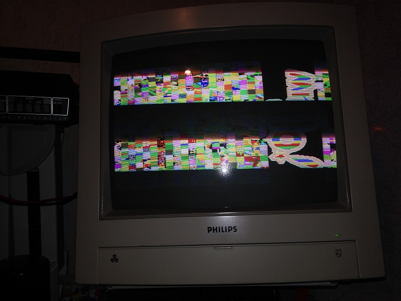
and now the gfx fault

mrd1.jpg


as I mentioned earlier it seems to be intermittent

anyone seen this before?

Lee2013-11-14 14:52:59
 

Anthony Graham

User
vacBacker
Credits
50CR
Hi, sorry should have clarified I have the fault you have after fixing the reset fault. I have the graphical glitching. Looks exactly the same as your last pic.

Ant
 

Lee

Active member
Feedback
6 (100%)
Credits
98CR
Anthony Graham said:
Hi, sorry should have clarified I have the fault you have after fixing the reset fault. I have the graphical glitching. Looks exactly the same as your last pic.

Ant

I can't remember exactly what I did to repair it I'll have to dig it out and have a look next week. Remind me mid next week about it.
 
Top