Namco Pacman Coin Pusher (2p)

myPinballs

Active member
Feedback
18 (100%)
Credits
731CR
Hi,

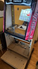
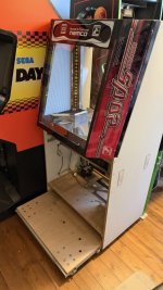
Just got myself one of these to fix up. Is a project one to repair and restore.

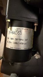
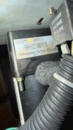
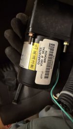
What i am after is some info on the push motor/gearbox. ie rpm ? Any info off an original woudl be handy. I see in the manual it was 100v orginally.

Thanks in advance. I am sure i will have many more questions to post here

Cheers
 

myPinballs

Active member
Feedback
18 (100%)
Credits
731CR
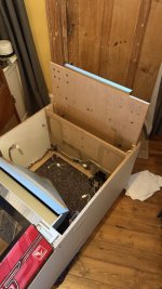
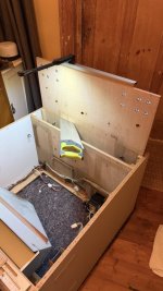
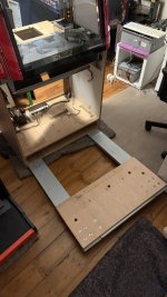
So i've set about dismantling this beast as it needs a full clean and refurb. As with the doodle jump machine i worked on awhile ago i am always interested to see if these old cabs can be adjusted to make private us more accessible. By studying the exploded diagrams in the service manual earlier, I worked out that some changes could be made to make it go through a std door much easier. Designing it as 810mm wide makes it somewhat tricky in alot of places..

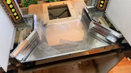
The chassis frame has 2 long steel frames that run down each side and attach with the castors. Pretty neat idea, so the bottom wood panel can be cut and made into 2 sections which are then slid back together & reattached by the frame caster bolts , then later strengthened by the lower cabinet sides and door parts. Simple and effective!

IMG_5789.jpgIMG_5791.jpgIMG_5794.jpgIMG_5795.jpgIMG_5798.jpg

This is how we look currently

IMG_5801.jpg
 

myPinballs

Active member
Feedback
18 (100%)
Credits
731CR
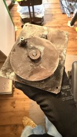
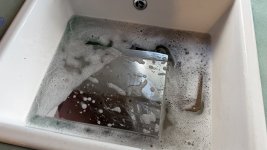
Cleaning continues. spent awhile cleaning the main panel, the bottom coin panel and the slide mechanism. The motor assembly was pretty dirty. I also worked out what kind of bearing i needed to have on the motor cam as this was originally a plastic one but has long since gone. I've managed to find a proper steel ball bearing that i think will work

I am also going to get a new front plastic made for the playfield where the coins run down.

IMG_5802.jpgIMG_5803.jpgIMG_5804.jpgIMG_5805.jpgIMG_5810.jpgIMG_5811.jpg
 

myPinballs

Active member
Feedback
18 (100%)
Credits
731CR
Power supplies!!!

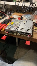
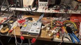
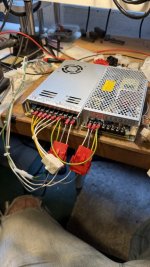
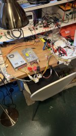
This project game was missing all the system 10 pcbs and all the power supplies. I need to get a full set of pcbs (motherboard, rom board and io board). But for Poer supplies I was ok altering the wiring harness to use 2 mean well switch mode psus that i already had on the shelf.

The power supply requirements are

+24v
+12v
+5v

So i used 2 supplies. 1 does the +24v and the other does the +12v and the +5v.

The wiring harness needs some changes so i opted to use my favourite connectors (amp mate n lok) and spade connectors to the actual psu terminals. Therefore meaning the psu can be unplugged if required easily.

I also need to make a pcb or assembly to switch the 100v for the bed motor. I think its jsut a basic really scenario that the pcb switches the replay at 5v to switch he 100v ac feed to it

IMG_5813.jpgIMG_5814.jpgIMG_5815 2.jpgIMG_5816 2.jpgIMG_5817.jpgIMG_5824.jpgIMG_5825.jpgIMG_5832.jpg
 
Top