Nintendo Space Firebird

simplesi

User
Credits
64CR
Hi,

I finally got my dream cocktail. Thanks for the heads-up Andy!

https://www.dropbox.com/s/3k1556ahp8jposk/20130310_182228.jpg

Anyhoo... got it home and had a wee nosey over it. The condition is reasonable. Internally it's actually quite clean and shiny. The boards look in good nick. It took me a wee while to figure out the sounds (not realising that there were two volume controls on two different PCBs. However, there is a problem that the monitor has collapsed.

Here's a linky to the video I took: http://www.dropbox.com/s/2ke2s4hvydakjw3/20130317_160750.mp4

I don't know if the sounds are correct, and I've no idea what's going on, on screen. The collapsed line, does change colour and it looks like there's things moving.

Any help and advice would be greatly appreciated. I know my way around a soldering iron, but the level of my understanding is basic so layman's terms would be good.
smiley9.gif


All original inside, with the Sanyo monitor.

Many thanks in advance.

Si
 

rigel

Newbie
Credits
73CR
It sounds to me that the game is playing, but the screen is not displaying it.

the sound of the guls appearing is there as is the gul movement sound.

when you fire and warp the sounds are correct as well so i think the game is playing offscreen.

i think your problem is somehow with the screen displaying action.

sorry i cant be more illuminating, i'm sure others will be.

regards, R.
 

guddler

Busting vectors like it's 1982!
vacBacker
Feedback
10 (100%)
Credits
4,058CR
You have a monitor fault known as vertical field collapse. Often caused by bad solder joints on an IC on the monitor chassis although I have no idea on specifics for that particular monitor.
 

simplesi

User
Credits
64CR
Thanks for the help. I saw that there's a Sanyo flow chart on the KLOV. Te first thing it asks to check is that the "service switch" is set to normal. Does anyone know where this is? I know where the "service button" is
smiley5.gif
for the game.
 

RaveN

Active member
vacBacker
Feedback
1 (100%)
Credits
1,325CR
Hi Simplesi

The Sanyo flowchart you are referring to is for the Sanyo 20 EZ, you will have the Sanyo 14-AZZ/14-EZW. The design is very similar to the 20-EZ, just with different components to handle the bigger tube. As a result, the flowchart is valid, but you'll have to check out the schematics and compare the different component numbers/values.

Here is the manual containing the schematics -> http://dl.dropbox.com/u/2897797/Sanyo14in.pdf

On your monitor, it doesn't have a service switch as such, but it does have a service jumper (a 2 pin plug). Make sure yours is in the following orientation:

sanyo.jpg


How are you with a multimeter and soldering?

Unfortunately, you're going to have to pull the monitor out, bench it and take some of the metal casing off (GND the HV first).

Like Guddler said, look for cold solder joints first, it may be an easy fix!!

Then check the V-hold and V-size pots, make sure they give appropriate values. Check the following solder points and cables that go to the seperate amp/pot adjustment board:

Black (point "FL"), Orange (FJ) and Grey (FK) for V-Hold

Purple (FM) - Vertical Size

Make sure you check the 50k pot (Vertical Size), it is vital that this reads a resistance of upto 50kohms, it drives the base of the vertical output transistors. It must not be closed/open circuit.

If that doesn't solve it, you'll have to dig a bit deeper.

You'll see a "TP91" point (as can be seen on tb lilley's post), you should have 105v DC there. The vertical output is created by T902-903 (2SD401A). If you can remove these from the circuit and conduct a diode test on each pair of legs. Also test the 2 diodes CR401 and 402, these are a common failure.

There are a few caps in that area that could possible cause Vertical collapse as well, have a check to see if any are leaking, especially C406.

If all of that checks out, it may be the oscillator IC, it will be either a LA1463 or LA1464, but I've never seen one go wrong yet.

A cap kit would be a very good idea whilst it's benched, it's a lovely colourful chassis when in good condition, but i'd hold off until you find the problem first.

Hope that helps,

Andy
 

rigel

Newbie
Credits
73CR
Si, how did you get the cabinate open? the listing said it was locked and the keys were lost.

is there a technique without having to drill?

regards, R.
 

virtvic

The Cabaret King
Feedback
21 (96%)
Credits
2,012CR
I have 2 of those monitors.

I recapped one the other day (which was working) when I put it back it had no display.

I reflowed all the pins on the neck board plug and it fired up straight away.

Look for bad joints.

Amazingly clean chassis there.
 

simplesi

User
Credits
64CR
Hey. It's looking a little cleaner now.
smiley1.gif
I've been a little slow of late... sorry Andy. I checked the wee adjustment board and low and behold... the vertical height pot won't register above 18.8kohms. So I take it that will be the first thing to check and replace? Where's the bet place for this?

Just wanted to check by what you meant about the open/close circuit?

I checked them... turned them one way to get 0ohms and then the other to get the max.

The solder looks fine. When you mean check for dry solder... what does it look like? Is it worth just runinng a solder iron across the existing solder joints on the back of the board?

Anyhoo. Look forward to hearing back from you.

The rest of the cab is going in for a paint job. Can't decide to go for matt finish or gloss of the Chocolate Brown. Any thoughts?
 

RaveN

Active member
vacBacker
Feedback
1 (100%)
Credits
1,325CR
Hiya mate,

Sorry for the delay, dry solder:

dry-solder-joints.jpg


The solder will likely look dull, and have a faint inside ring (where the solder has cracked and isn't making good contact). You often have to look very closely, if any look suspect wiggle the component a tad to see if the soldered leg moves.

The vertical height pot, are you able to desolder it and test it? It may give strange readings if you're measuring it in circuit.

"open" means that there's no complete circuit to test - for example if there's a break in a wire, your multimeter will show no reading, or "OL"

"closed" means the opposite, there is a circuit and in this case you should have 0ohms on the MM.

My money is on one of the 2 vertical transistors, if you can desolder them, you can run the diode test with your multimeter, follow the directions about half way down the page here: http://www.elexp.com/t_test.htm

Hmm tough one with the paint, I wouldn't go with Matt as they used to be quite shiny cabs, but maybe Gloss is *too* shiny, who knows, it will look great either way!

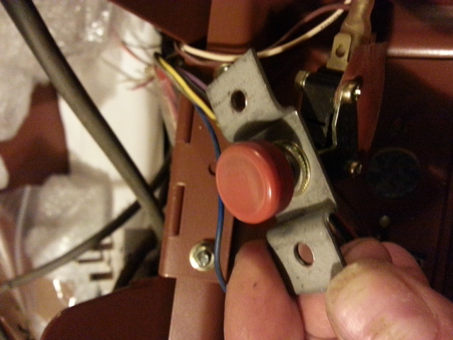
P.S - sorry, I don't have a spare button, I'm missing one myself. I spoke to Mikesarcade ages ago about it, he only stocks the upright nintendo buttons and never gets the smaller cocktail ones in.
 

RaveN

Active member
vacBacker
Feedback
1 (100%)
Credits
1,325CR
Hi Virtvic,

Out of curiosity, how much did it cost you to get it done?
Did they have a dark brown that was a good enough match? (I don't think we need to be too fussy when it comes to colour matching these old tables).

Cheers,

Andy
 

virtvic

The Cabaret King
Feedback
21 (96%)
Credits
2,012CR
I had it done thru work (for free!) But it would have cost 85 quid.
It was pricey, but the company does aircraft work and they stripped, prepped and painted the cab. They also masked all threads from paint.

I just guessed the paint colour (A numbered code) and it's no where near the correct colour, but I like it better 'milk chocolate' :)

I'll post a pic up later on tonight.
 
Top