Noob CRT question

Wintonmartin

Newbie
Credits
2CR
Hi all
I'm fairly new to this so hoping to get some advice.
I have picked up an old crt TV and currently have a jamma project cab I'd like to put it in. As far as a I know it's working.
Are the tube and chassis able to be connected to a jamma loom or do a need a suitable chassis?
Thanks in advance
20210629_180352_wecompress.com.jpg
20210629_180355.jpg
20210629_180319.jpg
 

yorkshire_spam

Active member
vacBacker
Credits
765CR
You should be able to connect the R+G+B+SYNC+GND from the jamma loom to the appropriate pins on the scart socket. I think you are supposed to put resistors in or something strictly speaking, but I've never bothered and it's always worked just fine.
Check out the scart pinout: https://en.wikipedia.org/wiki/SCART
 

John Bennett

Senior Member
vacBacker
Feedback
10 (100%)
Credits
5,332CR
Direct connection = saturated colours in some games and potentially overloaded game PCB output and TV input.

Resistors = ok colours but some games are overloaded.

Video op-amp = win.

edit: oh and TVs work great with arcade boards, I've been using them for decades.

John Bennett2021-06-29 21:35:48
 

Wintonmartin

Newbie
Credits
2CR
The scart adaptor looks like a nice an easy fix.

Whats an op-amp?

There's no frame on the tube but some old brackets in the cab. Any recommendations on making it fit? The tube is 18 x 14 and would be best placed vertical. Is it possible to flip the image via the hardware?
 

tb2000

Active member
Feedback
4 (100%)
Credits
3,579CR
The crt is an A51 Videocolor (FST) and 99.9% crts that are closest to this size in arcade cabs are A48, as such the average arcade monitor frame won't be quite big enough for this crt. With that said, if you can find a later made Intervideo crt frame you could use it as Intervideo and some other makes that made "clones" of Hantarex chassis used A51 FST crts when they became more common than A48 crts.

The other method is to just get a wood/MDF/plywood frame for it and mount the crt in that. You may have to get a piece of whatever material you want to use (any of those three listed above is fine) and make a crt sized hole in it, make sure it's the right size for the cab, then mount the crt in it and mount the whole thing in the cab.

Edit: In fact, thinking about it i'm pretty sure i've seen that exact model of CRT used on one of Intervideo's 21" monitors.

tb20002021-06-29 22:22:39
 

Monstermug

Active member
Feedback
23 (100%)
Credits
1,807CR
John Bennett said:
Direct connection = saturated colours in some games and potentially overloaded game PCB output and TV input.

Resistors = ok colours but some games are overloaded.

Video op-amp = win.

edit: oh and TVs work great with arcade boards, I've been using them for decades.

Got a sample video op-amp circuit buddy? (extra 2 points)
smiley2.gif
 

John Bennett

Senior Member
vacBacker
Feedback
10 (100%)
Credits
5,332CR
Heh, I was actually soldering up my own JAMMA->TV 'supergun' PCB as I typed that (bit too WIP to show off photos though).

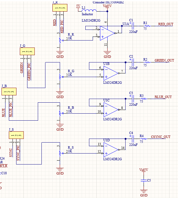
Here's the video circuit from it. There's a few ways to do it (@wintonmartin- an 'op amp' is an operational amplifier - you need any 14-pin device with a decent bandwidth - 20MHz+).

video_amp.PNG


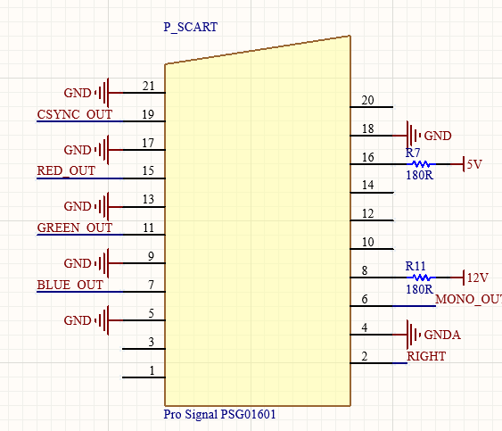
It's 4 identical channels - signal from board comes in on the left (ignore the yellow boxes and look at the potentiometer inputs), into a potentiometer to partially drop the voltage (and apply 1kohm of load to ground). The amplifier then just buffers it. Capacitors are on the output to make the signal AC as that's what TVs specify and there's 75 ohm resistors to match those in the TV. The 75 ohm resistors and the pot (set to 25-50%) will drop a 5V signal down to 0.7V for the TV

Take that off to the SCART connector and add 180 ohm resistors for blanking/mode stuff:

scart.PNG


I've pondered just doing standalone little video amp PCBs, might do at one point (open source).

John Bennett2021-06-29 23:50:04
 

Sbdesign

SEGA collector
vacBacker
Feedback
16 (100%)
Credits
1,721CR
You seem to know a lot about this John…So I’ll ask this here…

Do you know output of the model 2 boards?
I have a multi sync projector and it does 24khz

I have it working on model 3 through the vga on the cage
But have not had success from the 5 pin (or is it 4pin) rgb connector on either model 2/3 to vga.
It maybe the botch job I did wiring the vga ( wouldn’t rule it out)
Since then I do have some vga blanks I could use, but somewhere at some point I read I would need resisters? And so the task got side lined until reading this!

Lastly, if this is correct about resisters Does this mean the vga port on the model 3 is different to the 5pin rgb port (the one shared with model 2) and the filter board has these mods for vga port in place as standard?

Cheers for any input and guidance….

Sbdesign2021-06-30 00:06:09
 

John Bennett

Senior Member
vacBacker
Feedback
10 (100%)
Credits
5,332CR
Monstermug said:
cool a few resistors caps and a op amp. Got all those.

Just make sure it's a very fast op-amp - don't want a load of pixel bleed. I wouldn't fancy an audio amp like a TL084 - pixels are in the 6MHz region for 320x240, so get something really quick like 20MHz+.

I have to admit I haven't tried the circuit - will do tonight. I've used opmps for the RGB but ran the sync through a random 74HCT as a buffer in a past. But I can't see why it shouldn't work.

Don't forget to put a capacitor on the 5V/0V pins of the opamp - don't want noise on that messing things up.

Sbdesign said:
Do you know output of the model 2 boards?
I have a multi sync projector and it does 24khz

I have it working on model 3 through the vga on the cage
But have not had success from the 5 pin (or is it 4pin) rgb connector on either model 2/3 to vga.
It maybe the botch job I did wiring the vga ( wouldn’t rule it out)
Since then I do have some vga blanks I could use, but somewhere at some point I read I would need resisters? And so the task got side lined until reading this!

Model2 is not something I know that well, but did you wire the composite sync to the horizontal sync of the projector? (it might not like you wiring it to both H and V and it won't work wired to Vertical only)

I don't think resistors will usually cause a lack of picture, it's more to do with protection and signal level. Probably do want something in there long term though - arcade stuff is TTL levels (5V and something like 1k of impedance), whereas projectors, TVs etc are around 1V ac and 75 ohms, so if you wired it straight, you could be putting in voltages 5x to high to the telly and pulling 20x too much current from the game board. Or something like that - someone with more time than me can do the math(s).

 

Sbdesign

SEGA collector
vacBacker
Feedback
16 (100%)
Credits
1,721CR
Cheers John, I'll look into it further....

DtrXl.gif


I can't remember how I tried ages ago... but thinking if I ...

Wire the 5 pin filter to

R to Red

G to Green

B to blue

GND to Ground

Sync to Hor. Sync

Am I right in thinking It would be best to use pots inline on each of R,G & B?

Then have them turned right down, and tweak slowly until I get a picture to prevent the high voltage issue you mention?

Sbdesign2021-06-30 09:29:15
 

John Bennett

Senior Member
vacBacker
Feedback
10 (100%)
Credits
5,332CR
That wiring looks ok. You could just go with (the finger-in-air value of) 330 ohm resistors in-line with everything to start with (there's lots of scart-resistor bodge diagrams out there), including the sync.

Ultimately amplifier is where it's at once you get it working though. I'll add some to the to-do list (if folk think they're useful rather than full-blown 'superguns').

Worth saying, for anyone else reading, the above isn't going to allow Model2 to work on an actual PC VGA monitor - the projector is multisync using a high-density 15-way D-type, and supporting composite sync, to be specific ('VGA' is the wrong term, really, just shares the same pinout)
 
Top