PCB Prototyping

guddler

Busting vectors like it's 1982!
vacBacker
Feedback
10 (100%)
Credits
4,058CR
Does anyone have any experience or advice on knocking up prototype PCBs?

I want to make up 2 or 3 prototype Arduino shields for an Arduino Mega but I can't just go and buy an off the shelf one as I want my shields to hang over the end of the Arduino by about 2" and I've not seen any that do that yet.

The PCB(s) will need to be 5.5cm x 10cm each. They will need to have a pin spacing that matches the Arduino's ports which I think is 0.1"kk type spacing. I need to connect upwards of 35 I/O pins. So far all of them on the bottom edge of the Arduino Mega but I've sized the PCB such that it will reach all the ports.

At the moment I'm not adding any components, it's a simple task of mapping Arduino pins to an external DIP package. Ultimately I may well need to figure in some components for over voltage protection, maybe buffering and so on, but for now I was thinking I can get away with some sort of wire wrap type solution.

So can anyone help me here in terms of what I need to buy, from where and so on. When I've searched for wire wrap in the past it quickly becomes confusing as to what you're looking at, pitch spacing, suitability and son on.

Thanks in advance
smiley1.gif
 

Setch

The nice ad-min
vacBacker
Credits
542CR
Hi Martin

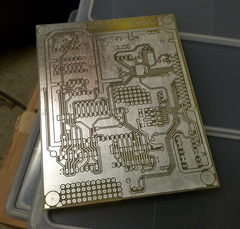
I've tried a bit of PCB etching with a Maplins kit & IRON on laser transfer sheets with varying success, it all depends on how complex the design is as I had very limited success with my more complex designs I was trying to produce.

I've since stopped involvement in that particular project but the next step was to start using the CNC machine at work, which apparently works well.

I have been meaning to try it out so if you have a PCB wizard template or similar I can see if I can feed it in as a test, I do have a half term coming up and the DT room will be free for me to get access.

I think Bloodf had a small batch of PCB's run recently by a proper company but not sure how much that cost him, I would imagine small runs are similar price to what I was looking at a few years ago £80+ each but things may have become cheaper now.
 

trm

Who loves you, and who do you love?
Feedback
2 (100%)
Credits
2,877CR
Hi dude. I just did a quick google for 'arduino shield eagle' and got plenty of hits for freely downloadable cad files covering a basic shield. I figure modifying one of these will remove a lot of the donkey work and you can just extend the base board to cover what you need. All the grind of placing the IO connectors is done :)

Obviously you'd need to get these etched & drilled but I'm guessing it'll still be quicker/cheaper/easier than researching and buying all the wire-wrap gear. Off the top of my head I remember the wire spool pens being quite expensive, plus given the size constraints I imagine wire-wrapping a shield would be a real PITA.

What are you making, or is it sekrit? There's a sticky at the top of Tech on places to get low run PCBs fabbed too.
 

guddler

Busting vectors like it's 1982!
vacBacker
Feedback
10 (100%)
Credits
4,058CR
You know what I'm making Tim!! I've got it working now
smiley1.gif
Mail me for more info.

OK, I'll have a look for the eagle files. The reason I was thinking about the wire wrap type solution is because I've only got probably one or two more evenings of coding and I will need to tear it all down and set it all back up again in a different configuration and it's a real pain so rather than tearing down 30+ jumper leads, plus a further 16 for the logic analyser, setting it all back up again in a different configuration and then having to repeat that multiple times I wanted to make something up nice and quickly so that once I've torn down that config, it's then a case of plug and play next time I want to do it.

So it's speed more than anything. I know exactly what I'm like (and I'm not alone in this), once I've worked out HOW to do something, it's not unusual for me to then never actually DO it. SO the less of a delay I have where I could lose momentum the better.

I did see a PCB kit in a box type thing where you laser print the design onto some special paper and then use a laminator or iron to transfer it to the PCB, followed by sponging on etchant. But I can't find it now. There was also some doubt whether my laser printer used plastic polmers (required), or a more modern toner makeup. I emailed the manufacturer and even then they were a bit unclear and I figured at £55 it was quite an expensive gamble to find my printer wasn't suitable!
 

Mitchell Gant

Active member
vacBacker
Feedback
2 (100%)
Credits
888CR
After I stupidly damaged my only Empire Strikes Back memory expander, I decided to have three of my own PCBs made to do the same function.

I used PCB Train, which is actually Newbury Electronics http://www.pcbtrain.co.uk

There are others, like PCB Pool.

They made me three boards for a total of £68 including delivery (£5) and VAT. Took a couple of weeks to get but was worth the wait to get the quality rather than make a mess with Veroboard, or wirewrap as you were suggesting.

Depends how much you want to spend really, and how confident you are that what you're getting made is electrically and mechanically correct. It's easy to spend a lot of money on PCBs that don't fit or have track errors. I've spent almost 25 years of employed life doing just that, ahem
smiley9.gif


If you have access to Eagle PCB designs that other folks have already proven, it does remove a large element of risk for you there. You'd just need to get familiar with Eagle PCB if you've not used it before.

2012-05-08_12.40.46.jpg
 

guddler

Busting vectors like it's 1982!
vacBacker
Feedback
10 (100%)
Credits
4,058CR
Cheers guys - some good stuff to look into.

Setch, I think I'll look into the eagle files and so on, then when I've got a "whatever is needed" sorted I'll come back to you on the laser sheets and the CAD etc. - cheers!
 

Adrian Purser

Moderator
Staff member
vacBacker
Feedback
2 (100%)
Credits
213CR
In the past I've always made my prototype PCBs by exposing the board to UV light through the artwork and then developing it. I used to get really good results even with double sided PCBs. I used to use Farnells PCB material which was coated in UV sensitive coating. I remember they changed the coating and since then the results were poor so I gave up on it.

I have had a couple of boards made using PCB pool and they were pretty good but that was a long time ago and I cant remember how much they were.

I did see some places on ebay offering PCB manufacture in China that seemed quite reasonable.

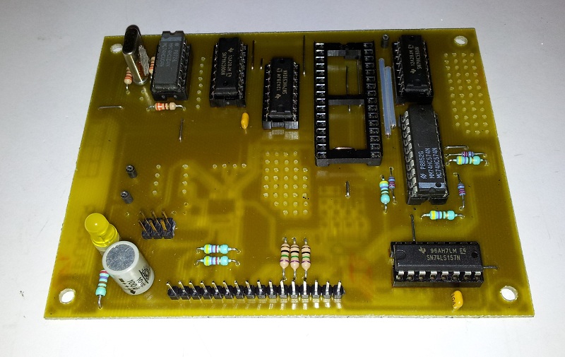
Last year I made a circuit for a tabletop. I used the laser printer toner with iron method. The results were pretty awful but it is most likely that my printer doesn't have the correct toner.

pcb.jpg


pcb2.jpg


I still have a bucket of ferric chloride somewhere but I got some different chemicals to etch the board from ebay and they worked really well.
 

guddler

Busting vectors like it's 1982!
vacBacker
Feedback
10 (100%)
Credits
4,058CR
Wow, have to say, this is really infuriating!!

So I spent the day today getting my head back around Eagle as I'd not used it since I designed the 9100 keyboard interface in 2008, and even then I only used it to draw the schematic. I never did create a PCB - maybe I should
smiley2.gif


So, I drew up my shield using one of the stock Mega templates and when it comes to routing the PCB, because of the size limit on the free version of Eagle and the fact that all the space on the Arduino is up the wrong end of the PCB I'm damned if I can get it to route onto a single layer PCB. I did once, thought I'd have another go as I was still experimenting with how it worked at that point and now I'm damned if I can get it to route again. Arse!

I think I'm going to have to start again and this time work out how to create a new part that is effectively the Mega shield all shifted over to the left. Not sure how to do that yet.

By the way - Ade, that PCB that you posted the picture of and said you thought it was pretty awful - I'd be very happy with those results
smiley36.gif
 

Muppz

Active member
Feedback
6 (100%)
Credits
362CR
I've been using these folks http://www.pcbpanel.co.uk/ since PCBtrain hiked their prices for what I needed.

Not the cheapest but service and response to questions was fast. For the last boards (for custom chip re-engineering) their tolerances allowed me to cram more pcbs onto a panel than some of the other offerings, got 3 extra on a panel which bought the price down to an affordable price.

Using easypc and exporting the gerbers, not sure if they take straight eagle files.

Ade did you use those tinning crystals on that board? I never got that good a finish when using those.
 

Muppz

Active member
Feedback
6 (100%)
Credits
362CR
Setch said:
I have been meaning to try it out so if you have a PCB wizard template or similar I can see if I can feed it in as a test, I do have a half term coming up and the DT room will be free for me to get access.

Now you got me thinking maybe I should go buy the DT techs here a coffee sometime this week and sweet talk them into letting me have a go on their denford while the robotics class students are away.
smiley20.gif
 

guddler

Busting vectors like it's 1982!
vacBacker
Feedback
10 (100%)
Credits
4,058CR
So, I worked on this until about 2am last night. I'm damned if I can get it down to a single layer board. The space restrictions were driving me insane on Eagle so I also re-did it in DesignSpark PCB which is RS Components tool. There's some really nice features in that like the ability to add components to the schematics using RS part numbers and so on but to be honest when it came to board layout it wasn't a patch on Eagle. I tested just joining one pin of a socket to one pin of the Ardunio and unless I forced single layer and vias it added a via and put half the track on the bottom, half on the top. I couldn't see any reason for that whatsoever!! On top of that, it insisted on routing everything around every connector whereas Eagle would route between the pins of the connectors. So I ended up not knowing which was right and which was wrong.

So it looks like I'm talking £50(ish) for a single board of 10cm x 8cm or less. Bearing in mind there's no components, it's just a simple wiring adapter that too much.

So what other options do I have? Setch, can your CNC machine do two sided? Or is that a no-no?

If not, I think I'm likely to end up back with veroboard and wire wrap!
 

Adrian Purser

Moderator
Staff member
vacBacker
Feedback
2 (100%)
Credits
213CR
Muppz said:
Ade did you use those tinning crystals on that board? I never got that good a finish when using those.

Yes. I've used them before and usually get good results. I used them because I had some surface mount components and was hoping that it would make it easier to solder but in reality the whole board was a pain to solder and I have no idea why. The avr that was supposed to be on the board was impossible to solder. I even tried using a flux pen.

@Guddler: I've never really got on with auto routers. I usually route boards manually. It's usually inevitable that you will have to use jumpers on single layer boards. I have made double sided boards before and they work quite well but you obviously don't get vias or through plating unless you are really hardcore and I'm just not. I usually cheat and use IC socket strips which allow you to solder on both sides of the board. You used to be able to buy pins that you would put into the hole and let you solder on each side. A kind of poor mans via but I'm not sure if you can still get them.
 

guddler

Busting vectors like it's 1982!
vacBacker
Feedback
10 (100%)
Credits
4,058CR
Here's that PCB solution I mention - finally found where I spotted it:
http://www.pcbfx.com/main_site/pages/start_here/overview.html

Still not overly cheap - it comes in at about £70 shipped and then you still need to either buy a laminator or struggle with an iron. BUT, for that £70 you get 2 A4 sheets of single sided PCB and 2 A4 sheets of double sided so considerably more than you'd get for the same money from a fab shop.

Problem is, there's doubt as to whether my printer is suitable (bloody typical!)
 

cliff_poole

Active member
vacBacker
Feedback
6 (100%)
Credits
1,069CR
There is the photo resist method, although you do need a UV light box.

Print your artwork on to a transparency. The board with a photosensitive coating comes with a plastic covering which you peel of and put in the UV light box with your transparency. Once exposed (I don't remember timing), the PCB goes into a bath of developer which washes off the photosensitive resist that was exposed.

I haven't done it for many years so don't even know if the kit to do it is still available.
 

Muppz

Active member
Feedback
6 (100%)
Credits
362CR
Mesmeric_G said:
There is the photo resist method, although you do need a UV light box.

Print your artwork on to a transparency. The board with a photosensitive coating comes with a plastic covering which you peel of and put in the UV light box with your transparency. Once exposed (I don't remember timing), the PCB goes into a bath of developer which washes off the photosensitive resist that was exposed.

I haven't done it for many years so don't even know if the kit to do it is still available.

And remember to reverse print or you end up having to mount the parts on the copper side. Speaking from experience here
smiley19.gif
 

guddler

Busting vectors like it's 1982!
vacBacker
Feedback
10 (100%)
Credits
4,058CR
That's very tempting being as Yeovil's not that far away but it's something I know just wouldn't get used enough. And I'm just heading away for work in the morning so won't be about for a bit either.guddler2013-02-18 02:01:06
 

guddler

Busting vectors like it's 1982!
vacBacker
Feedback
10 (100%)
Credits
4,058CR
OK, just to resurrect this - does anyone have the ability to print me a single sided PCB, 160x100x1.5mm for suitable re-imbursement?? Layout file is available as PDF ready for printing.

If you can print me a double sided then it would be even better but I can live with single sided.

Thanks,
Martin.
 
Top