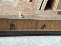
Atari - Centipede 01 - part 7
The mounting edges and coin box areas are the next sections to get worked on.
Starting by cutting the coin box back and side sections. These also have a number of wooden brackets glued and pinned to them, which help fix the box together, and mount it to the base and front of the cab. There are also brackets just set inside the top of the sides which is what the coin tray sits on.
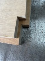
The sides also have a notch out of the lower front corner. This is to allow clearance for the bottom front support bar that helps attach the front panel to the base.
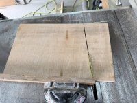

Brackets are then cut and glued to the bottom edge of the coin box sides.
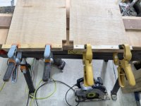
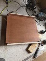
To attach the front, back, and side mounting edges to the bottom of the cab, I created yet another wee jig. The mounting brackets are set in by 20mm at the corners. This allows for the front and side brackets to be slotted in. A simple 20mm block of wood set into the corner of two short strips, keeps this consistent, and stops you have to stop and measure every time.
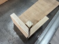

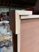
So we now have all the mounting brackets glued and pinned into place. I'll want to add a few screws to the underside, just for some added strength.
Setting the pieces for the coin box area into place, and you can see the whole base section coming together rather nicely.
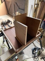
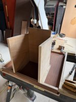
The lower back section will be next, and get the front finished off. Should be able to mount these to the base, then comes the side sections to be filled and sanded, along with the t-moulding groove.