PLCC Socket change

jonhughes

Active member
vacBacker
Feedback
52 (100%)
Credits
1,156CR
Hi guys,

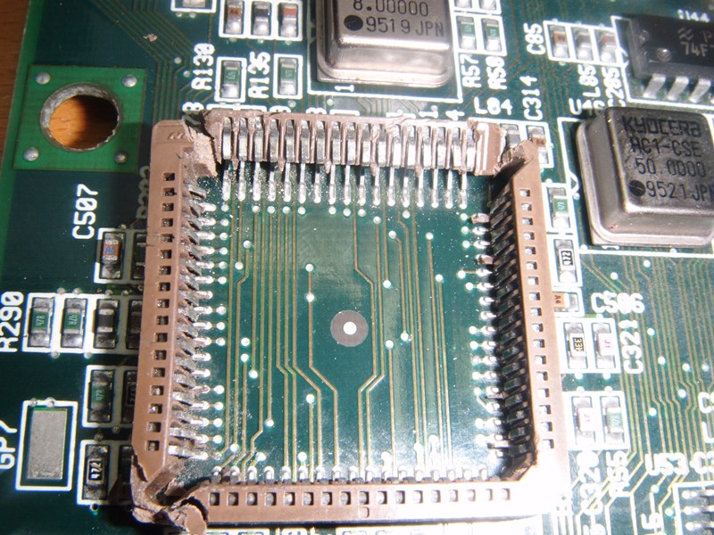
I have a UMK3 PCB which is faulty. The PLCC socket at U45 is affected by corrosion and the pins in the socket are heavily oxidised. I've attacked them with a fibre glass pen but to no avail. When I push down and manipulate the chip with heavy pressure. I get a response from the board, but it's still not enough to initiate a boot.

It did boot yesterday for the very first time but didn't get beyond the test screen. Today, it's black screen day again.

Is there any process that can remove this socket - hot air works for example? I'm happy to have this one fixed if possible, would be nice to have this working. The socket appears to be the stumbling block and is surface mounted on the PCB, and there's no way I can do that repair.

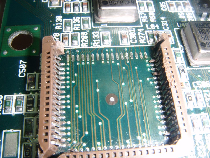
MK3_socket.JPG
 

silverfox0786

Beware the Hillman
Feedback
47 (100%)
Credits
2,699CR
i seen the guys do this on an Amiga whin istalling a socket for the FPA chip

they usually cut out that central support pad so the pins are then visible and easily accessed

do the same with a fine side cutter so you have access to the pins to remove it
 

jonhughes

Active member
vacBacker
Feedback
52 (100%)
Credits
1,156CR
Hi Sarj,

I've seen the video on U-tube also. It's a bit on the risky side for me. If there's no response I guess that's the only option available for it.

P.S. the Fingerboards are great.

Cheers
 

jonhughes

Active member
vacBacker
Feedback
52 (100%)
Credits
1,156CR
Ok, I don't work on SMS stuff and I think I've only ever tried a few times before and was never happy - but that was a long time ago.

I've decided, well f**k it - I'll give it a go.

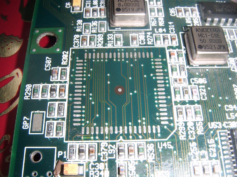
First off cut out the base like and release one side of the socket.

UM1.JPG


Release the pins and one side is free.

UM2.JPG


Repeat for all side and it's off.

UM3.JPG


It only took me 20 minutes to remove. I'm considering that was the easy bit - putting a new one back in is going to be the hard bit. I can see me scorching the top of the socket with the iron and easily bridging those pads.

I'm ordering a new socket.
 

silverfox0786

Beware the Hillman
Feedback
47 (100%)
Credits
2,699CR
glad they arrived safe mate

and looks like you done a good job there removing it too

another trick to putting it back on is to cut away the central area

its there for support yes but once the PLCC is fitted and as long as your not planning to remove it again and again its gonna be fine

it will make soldering it in much easier using Pauls recommendations
 

jonhughes

Active member
vacBacker
Feedback
52 (100%)
Credits
1,156CR
PaulSwan said:
A 1/64" tip for your iron and a lighted magnifier arm will make it a breeze and is well worth the investment.

Paul.

Thanks for the advice. Could I ask a few questions please?

1) When putting my new socket back in, would you 'prime' the solder pads with solder before positioning the socket ready to be soldered into place? I just imagine (although don't know yet) this would generate a better bond to the pins. The alternative being, I just leave the pads 'clean' and then start soldering with the socket in position.

2) If I had the correct equipment, I'm imagining that 'priming' the pads and then installing the socket (complete with base) using hot air flow would be the best and complete way to fix the new socket?
 

obcd

Active member
Credits
3,830CR
It depends what you mean with 'prime'. You normally would need to add some solder paste to the pads. If you prepare them with a bit of normal solder, the hight of the pads will become unequal and it will be difficult to correctly position the socket. Once the solder is heated up, the socket needs to move down a little to make contact with the tracks instead of the solder, which is again rather tricky. Even if you prime with solder paste, the amount of paste you use is a critical parameter for a good result.

Make sure all solder pads are clean, and use some solder flux to ease the soldering.

If you intend to use a solder iron with fine tip for the soldering, check that all pin's of the socket are accessible. (But I have a feeling you already did that)
 

Ordyne

Active member
vacBacker
Feedback
5 (100%)
Credits
1,282CR
Get the appropriate tip (id say small hoof or knife tip) cut the centre out of the new socket if you need to do it for access, place the socket and then solder a couple of pins from corner to corner, then solder using the drag method and plenty of rework flux. Dont put solder on the pads before hand!

If you don't need to use hot air then don't do it.. One you need to be using a thermo couple to see what temps your getting on the pcb/device and two your going to end up heating other components up which you can avoid by soldering it by hand.
 

jonhughes

Active member
vacBacker
Feedback
52 (100%)
Credits
1,156CR
Thanks for the advice, again. Hope I'm not bugging but I'll be back with another question on surface mount soldering regarding RAM chips. Makes me wonder how they get those sockets on in the first place. The pad solder priming question may become a little clearer when I post the image of these RAM chips and why I asked. Will post them soon.
 

tb2000

Active member
Feedback
4 (100%)
Credits
3,579CR
I use the method Ordyne describes above (mainly to cut the centre out and tack one or two pins in each corner). I had to put a small PLCC socket on a Midway Seattle pcb recently that I converted from one game to another for someone. Luckily though I didn't have to remove a socket, only the chip that was soldered on and for that I used Chipquik.
smiley1.gif
 

Ordyne

Active member
vacBacker
Feedback
5 (100%)
Credits
1,282CR
Im going to guess that there's some unused pads on some ram locations you've seen and these have solder on them ?

Part of the production process means that everything that is covered with soldermask gets soldered, if you look up wave stations and the process you will get the idea :)
 

jonhughes

Active member
vacBacker
Feedback
52 (100%)
Credits
1,156CR
Hi, thanks for the input.

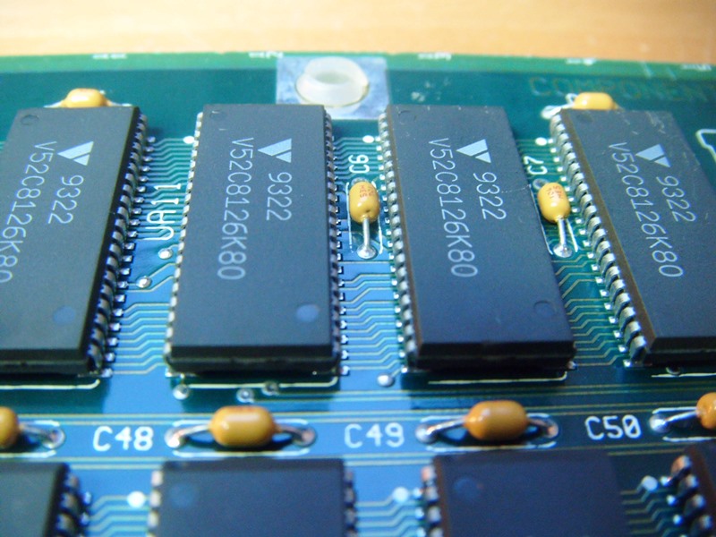
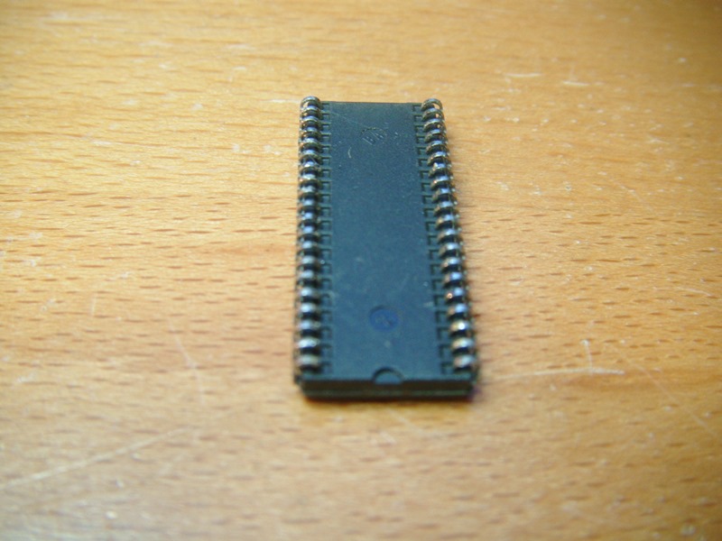
Yes I have used quick chip to remove these types of RAM chips. This particular set is from a Mortal Kombat 2 board. I managed to remove those chips with quick chip but I'm purely out of ideas on how to solder the new RAM chip to those pads underneath. There must be half a mm showing on the pad once you place the chip on top. The contact points are another 2mm away from that. Then there's the incline of the soldering iron required to miss the adjacent ram chip.

Holding the iron at a steep incline just makes it totally easy to bridge every single pin along the RAM chip. Those chips are about 10mm across, to give you an indication of the gap - we're talking a 3mm gap at least to poke the iron into.

How is this one done? I always thought hot air was the only way.

SMS1.JPG


SMS2.JPG
jonhughes2015-07-13 21:25:39
 

terminator2k2

Active member
Feedback
1 (100%)
Credits
327CR
I was going to say, hot air blower and solder paste

I usually use my gas soldering iron with the blower nozzle on.

just an example

https://www.youtube.com/watch?v=f_yFDpSTfaoterminator2k22015-07-13 21:38:29
 

jonhughes

Active member
vacBacker
Feedback
52 (100%)
Credits
1,156CR
This is what I imagined it would be like. The 'primer' (as I describe it), in this case wouldn't be solder but solder paste then re-flowed with the hot air tube.

https://www.youtube.com/watch?v=f_yFDpSTfao
 

jonhughes

Active member
vacBacker
Feedback
52 (100%)
Credits
1,156CR
Thanks for the offer, I may just have some though in the chip quik set. It gives me an idea though on the hot air pencil. If there is a portable version (handheld) rather than an entire station like the one in the video. I may just be ok.

I'm going to do a bit of research, thanks.
 

tb2000

Active member
Feedback
4 (100%)
Credits
3,579CR
With those rams, what i'd do would be to tin the pads first so they've got slightly raised solder blob on them, then place the chip on top and use a soldering iron with a longer thinner tip on to briefly heat each leg. Should only take a couple of seconds on each one if it's hot enough (but not too hot!)
 
Top