Seeing as there's a lot of techies on this site, I thought some of you might have gone out and bought yourself a raspberry PI.
If so, I thought I'd share a project I'm working on at the moment. I'm in the midst of creating a cut down version of a Fluke. The general idea is to interface the Rpi with an arcade board so that it can perform a variety of tests, consisting of:
1) Check the accuracy of the clock.
2) Read the entire memory map and because it can do this:
Read/check all eproms
Read/Write check of the ram
Test the ram/rom buffers.
3) Check RESET, interrupts and bus control lines.
4) Possibly - Attempt to display to screen by writing to the video ram.
5) A pin acting as a logic probe.
The idea at the moment is to have enough input/outputs (both normal and High Imp capable) to cater for the older CPUs, so I have enough for Z80, 8080A, 6502 and 6509 etc..
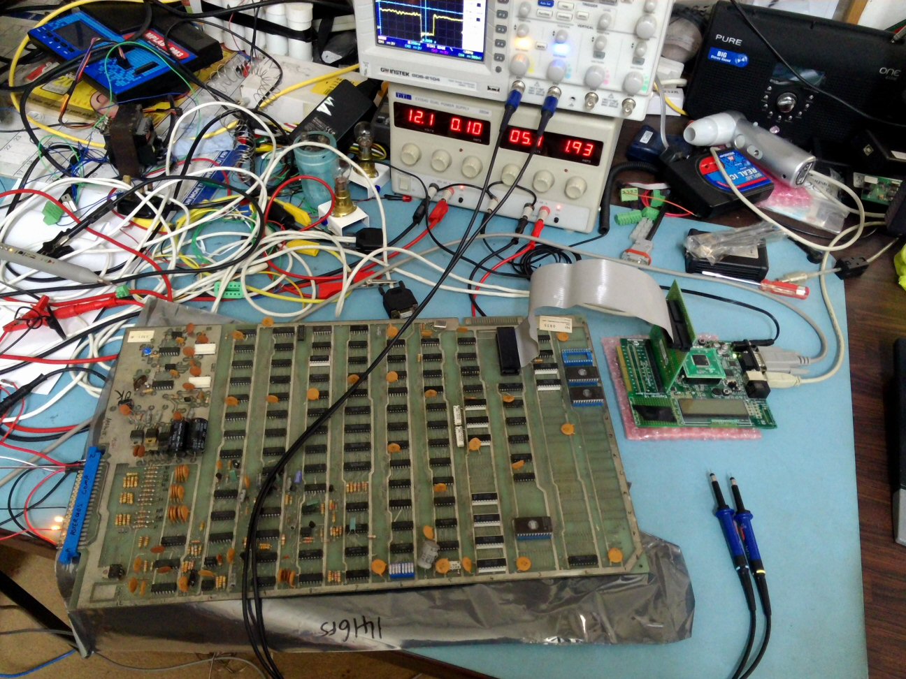
Although the breadboard looks a mess of wires, a manufactured board with SMD components would be a fraction of the size.
The chips you see simply perform the following functions:
1) I/O Expanders (to increase the I/O pins of the Rpi)
2) 3.3v (Rpi) - 5v interfacing
3) TTL / CMOS conversion.
Whilst something like this won't ever come close to say a Fluke 9010A, it may be useful if it's cheap enough, more user friendly, expandable (i've already made a daughter board so it can program 2708/2716/TMS2532 eproms(the ones my mainstream eprom readers can't do)).
A few years back I had a similar project using a PIC18F4550, it used USB to interface with a PC, the problem with that I found is a) you needed a degree in the USB stack to program it, and b) It was still OS specific and my C programming sucks.
At least with this it can Rpi dependent, easy and cheap to buy, and it's written in simple Python.
Sorry the photo is poor, I only have my phone on me at the moment:

Anyway, what do you guys think, any tips or advice?
Cheers,
Andy
RaveN2013-05-04 01:26:48
If so, I thought I'd share a project I'm working on at the moment. I'm in the midst of creating a cut down version of a Fluke. The general idea is to interface the Rpi with an arcade board so that it can perform a variety of tests, consisting of:
1) Check the accuracy of the clock.
2) Read the entire memory map and because it can do this:
Read/check all eproms
Read/Write check of the ram
Test the ram/rom buffers.
3) Check RESET, interrupts and bus control lines.
4) Possibly - Attempt to display to screen by writing to the video ram.
5) A pin acting as a logic probe.
The idea at the moment is to have enough input/outputs (both normal and High Imp capable) to cater for the older CPUs, so I have enough for Z80, 8080A, 6502 and 6509 etc..
Although the breadboard looks a mess of wires, a manufactured board with SMD components would be a fraction of the size.
The chips you see simply perform the following functions:
1) I/O Expanders (to increase the I/O pins of the Rpi)
2) 3.3v (Rpi) - 5v interfacing
3) TTL / CMOS conversion.
Whilst something like this won't ever come close to say a Fluke 9010A, it may be useful if it's cheap enough, more user friendly, expandable (i've already made a daughter board so it can program 2708/2716/TMS2532 eproms(the ones my mainstream eprom readers can't do)).
A few years back I had a similar project using a PIC18F4550, it used USB to interface with a PC, the problem with that I found is a) you needed a degree in the USB stack to program it, and b) It was still OS specific and my C programming sucks.
At least with this it can Rpi dependent, easy and cheap to buy, and it's written in simple Python.
Sorry the photo is poor, I only have my phone on me at the moment:
Anyway, what do you guys think, any tips or advice?
Cheers,
Andy
RaveN2013-05-04 01:26:48