Rastan Saga

jonhughes

Active member
vacBacker
Feedback
52 (100%)
Credits
1,156CR
I have a Rastan Saga board for repair. On power up the board looks as if it is going to boot up. The screen fills with graphics and then turns black and the board continually begins rebooting, on each cycle there is a very thin strip of red pixels and this then repeats over and over.

I'm looking for the schematics and can only find those for Rastan. I've printed those and have begun trouble shooting components but am finding quite a few discrepancies. Which is leading me to think are the schematics the same for Rastan and Rastan Saga?

Can anyone help me with this one?jonhughes2013-11-17 12:08:08
 

Equites

Chief Sheesher®
vacBacker
Feedback
35 (100%)
Credits
3,329CR
jonhughes said:
I have a Rastan Saga board for repair. On power up the board looks as if it is going to boot up. The screen fills with graphics and then turns black and the board continually begins rebooting, on each cycle there is a very thin strip of red pixels and this then repeats over and over.

I'm looking for the schematics and can only find those for Rastan. I've printed those and have begun trouble shooting components but am finding quite a few discrepancies. Which is leading me to think are the schematics the same for Rastan and Rastan Saga?

Can anyone help me with this one?

Rastan and Saga are the exact same hardware, just different ROMs.

Sounds like your PCB is watchdogging, you could start by checking voltages, reseating ROMs, checking ROMs?
 

jonhughes

Active member
vacBacker
Feedback
52 (100%)
Credits
1,156CR
Ok, I agree it would be strange to have different hardware for what is basically the same thing. I've done all the usual things but here's one thing that is puzzling:

On IC25 (68000) on the first page of the schematics pins 14 & 49 are connected to a 5V supply. They're getting practically zero on the meter. I can't see any traces leading to pins 14 & 49, so can't see how they are supplied by 5V (unless I'm totally missing something).
 

trm

Who loves you, and who do you love?
Feedback
2 (100%)
Credits
2,877CR
Inside the PCB there will be an entire hidden copper layer which is connected to 5V. So the Vcc pins you mention will go into the board and then be connected to the power layer.

What actual readings are you getting for 14 & 49 and what are you using for your ground point. Can you measure the resistance between the two pins with the power off - you should find it's very, very close to zero ohms.
 

Equites

Chief Sheesher®
vacBacker
Feedback
35 (100%)
Credits
3,329CR
jonhughes said:
Ok, I agree it would be strange to have different hardware for what is basically the same thing. I've done all the usual things but here's one thing that is puzzling:

On IC25 (68000) on the first page of the schematics pins 14 & 49 are connected to a 5V supply. They're getting practically zero on the meter. I can't see any traces leading to pins 14 & 49, so can't see how they are supplied by 5V (unless I'm totally missing something).

I think you are looking at the wrong place unless the CPU is not working, quite rare to find a failed 68000. In the first instance, I would be checking ROMs (common failure) and the CPU RAMs.
 

jonhughes

Active member
vacBacker
Feedback
52 (100%)
Credits
1,156CR
trm said:
Inside the PCB there will be an entire hidden copper layer which is connected to 5V. So the Vcc pins you mention will go into the board and then be connected to the power layer.

What actual readings are you getting for 14 & 49 and what are you using for your ground point. Can you measure the resistance between the two pins with the power off - you should find it's very, very close to zero ohms.

Ok, I did what you said and measured the resistance.

Pin 14 - 77 ohms first attempt, 15 ohms next attempt, varies to whatever it feels like.

Pin 49 - off the chart, the meter is self scaling and it's going into Mohm territory.

Pin 14 now is outputting 5.1V steadily, while pin 49 is fluctuating between 2V and 0.1V at the board resets.

You learn something new, I had no idea boards were dual layered. And I almost forgot there are pins labelled GND throughout the board. I tried various ones and at the JAMMA connector - same results.jonhughes2013-11-17 19:50:38
 

jonhughes

Active member
vacBacker
Feedback
52 (100%)
Credits
1,156CR
Equites said:
jonhughes said:
Ok, I agree it would be strange to have different hardware for what is basically the same thing. I've done all the usual things but here's one thing that is puzzling:

On IC25 (68000) on the first page of the schematics pins 14 & 49 are connected to a 5V supply. They're getting practically zero on the meter. I can't see any traces leading to pins 14 & 49, so can't see how they are supplied by 5V (unless I'm totally missing something).


I think you are looking at the wrong place unless the CPU is not working, quite rare to find a failed 68000.  In the first instance, I would be checking ROMs (common failure) and the CPU RAMs.

You do have a point on the ROMs. Although the sockets are populated I have no idea if the ROMs are in their correct positions.
 

jonhughes

Active member
vacBacker
Feedback
52 (100%)
Credits
1,156CR
trm said:
Inside the PCB there will be an entire hidden copper layer which is connected to 5V. So the Vcc pins you mention will go into the board and then be connected to the power layer.

What actual readings are you getting for 14 & 49 and what are you using for your ground point. Can you measure the resistance between the two pins with the power off - you should find it's very, very close to zero ohms.

I misread the post: the resistance between pin 49 & pin 14 was off the scale (now 1.4 Mega ohms), while the resistance between pin 49 and the 5V at the JAMMA connector is also 1.4 Mega ohms. Pin 14 is reading 0.7 to 0.2 ohms.jonhughes2013-11-19 11:03:44
 

trm

Who loves you, and who do you love?
Feedback
2 (100%)
Credits
2,877CR
OK, that's a bit weird. 49 and 14 are both Vcc and should be a fraction of an ohm. Sorry for the cheeky question but are you definitely sure you've got the pin count correct?
smiley9.gif


If the data is indeed correct I'd want to find out why one of your Vcc supplies doesn't seem to be connected. Even if pin49 is soldered into free air I'd expect less than 1M4 to Vcc!

Can you measure the resistance of pin49 to ground? If it's not a dead short I'd consider wiring 5V to pin49 and seeing what happens. It could be a fried 68k anyway so you probably can't make it worse. Does the CPU act like a one bar electric fire when it's powered up?
 

jonhughes

Active member
vacBacker
Feedback
52 (100%)
Credits
1,156CR
trm said:
OK, that's a bit weird. 49 and 14 are both Vcc and should be a fraction of an ohm. Sorry for the cheeky question but are you definitely sure you've got the pin count correct? 
smiley9.gif


If the data is indeed correct I'd want to find out why one of your Vcc supplies doesn't seem to be connected. Even if pin49 is soldered into free air I'd expect less than 1M4 to Vcc!

Can you measure the resistance of pin49 to ground? If it's not a dead short I'd consider wiring 5V to pin49 and seeing what happens. It could be a fried 68k anyway so you probably can't make it worse. Does the CPU act like a one bar electric fire when it's powered up?

No offense taken, after all you don't know my ability like I don't know my ability either. I'd say I'm below average, if at all that good.

You're right though, I am counting them wrong, now I feel a little silly doing this from my poor memory. It seems I'm counting the right side starting from the top instead of the bottom.

The CPU is warming up but it's not scalding yet. I'll re-start the process once I get some free time, but thanks for pointing me in the right direction.jonhughes2013-11-19 12:06:23
 

trm

Who loves you, and who do you love?
Feedback
2 (100%)
Credits
2,877CR
No problem Jon. I can't remember the number of times I've thought I'm on to something when I don't see an expected signal on a pin, have reached for the cutters, double-checked my counts just to be certain, and then had to put the cutters back :(

Given the board has schematics it's pretty easy for us to give you some guided troubleshooting assistance if you want it, so post back when you have time and we'll help out!

cheers

tim
 

jonhughes

Active member
vacBacker
Feedback
52 (100%)
Credits
1,156CR
Thanks, I've been doing this for a while too but not anything for at least 6 months. I'm going through a bulk buy - repaired an NBA Jam TE board, a damaged MK2 sound board and a Mortal Kombat PCB. Then I forget which way the pins are labelled. I'm going on holiday to the Canaries in five weeks and I think I need it.

Cheers.
 

jonhughes

Active member
vacBacker
Feedback
52 (100%)
Credits
1,156CR
Ok, I've had another look and found some anomalies. Unless it is me, once again.

LS11 is a SN74LS11N and located at IC61 on the board.

LS08 is SN74LS08N and located at IC64 on the board.

On the first page pin 2 is shown as an input, it's actually pin 3 on the chip diagram and confirmed by continuity. Pin 9, 10 & 11 are also shown as inputs but that is for IC 64 shown as LS11 but it's actually the LSO8 chip.

Aside though, pin 26 (FC2) on IC25 is stuck high while pin 28 (FC0) and pin 27 (FC1) are pulsing.

74LS11.jpg


74LS11-1.jpg
jonhughes2013-11-19 16:53:19
 

jonhughes

Active member
vacBacker
Feedback
52 (100%)
Credits
1,156CR
Not one to give up......I think I might have caught this one. I was logic probing the board and found IO (1-F5) was dead at 3 locations.

Pin 5 on IC83.
Pin 19 on IC85.
Pin 28 on IC48.

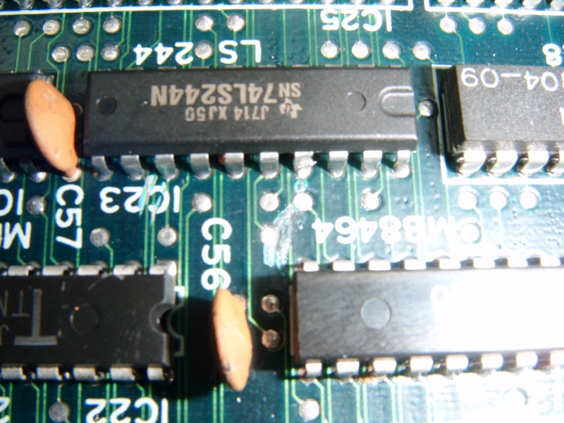
I can't work out where IO (1-F5) comes from but I traced continuity to this position, where the trace is completely scratched out. Can someone with a board confirm where this leads to, please? I can't check it beyond the scratch.

DSCF7092.JPG
 

jonhughes

Active member
vacBacker
Feedback
52 (100%)
Credits
1,156CR
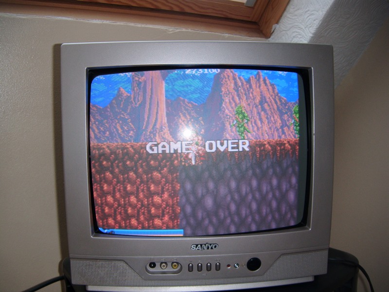
I decided to make a bridge across the scratch. It took me quite a few attempts, I will tell you that much, but I eventually got there. Finally it has worked. It's not my neatest creation but the game is running. It began resetting initially but has progressed - indicating a capacitor problem possibly?

Happy but it had Rastan Saga on the board label and it turns out that it's just a Rastan board.

Rastan_1.JPG


Rastan_2.JPG
 

jonhughes

Active member
vacBacker
Feedback
52 (100%)
Credits
1,156CR
Thanks, I'm going to play test for a while and see if it is fine. It has stopped re-setting now. I've had it running straight for two hours on my test bench.

I really would like to burn this to a Rastan Saga board, since this is the one I used to play way back. Can you let me know which ROMs need to be burned. I hope it's the erasable ones. Don't think my burner is any good at reading those masked ones.

Any help greatly accepted.
 

jonhughes

Active member
vacBacker
Feedback
52 (100%)
Credits
1,156CR
Top