This is different from my previous Model 2A fix log, so thought I'de do a new thread.
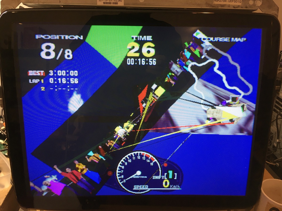
I got this Model 2A board recently from MysticMonk and put it on the repair bench for a look. The board stack was sold as faulty with graphic clitches and sure enough there were polygons with their points flying everywhere.
The graphics board looked pretty clean and had zero sign of repair which for me is quite uncommon, there are usually signs of reflowing or chip replacement or even factory issued repairs with patch wires fixing broken traces.
No signs of dust collecting around the polygon memory ram chips, no signs of the board having been cleaned. Maybe it was kept in a very clean environment, or had died pretty early in life and had been shelved all this time.

So the first thing I did in this area was to use an oscilloscope to probe all the address, data bus and control lines to see what the activity is like on all the memory chips and find anything obviously wrong.
Here's the pinout of the polygon ram chips (TC518128 on this particular board).
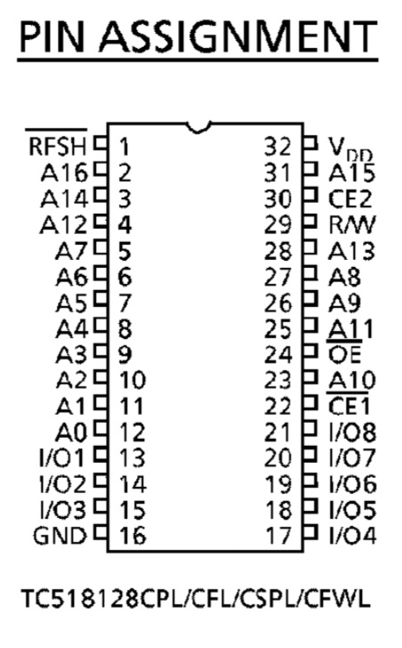
Pretty quickly I found that address line A13 (pin 28) which is applied to all six chips seemed to be stuck low constantly, it wasn't at completely ground potential of zero volts, it appeared to be around 0.2v and also seemed to have a bump of noise that bought it up to 0.5v every start of the 60hz video picture redraw.
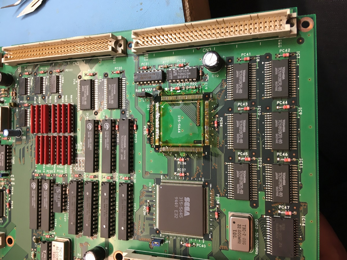
I checked A13 with a multimeter to see if had continuity with ground but from seeing the slightly noisy signal I'de guessed correctly that it wasn't shorted to ground and was either being pulled low by a faulty ram chip or wasn't being driven properly by what I assume is the polygon memory management chip nearby which is IC1, a Sega custom chip numbered 315-5644 which has the markings of a Fujitsu manufactured chip (specifically the font used on the numbers).
I decided to take the plunge and replace this custom chip using one that I'de got from my spares board that has different issues.
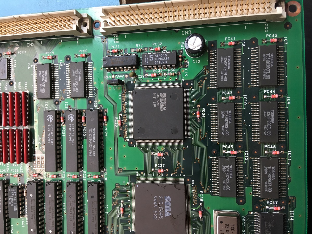
So I desoldered the possibly faulty IC1:
And grabbed this one from another board:

Now fitted:
Powered the board up with the custom chip replaced and noticed an immediate improvement, but not a complete fix so some other problem was still occurring:
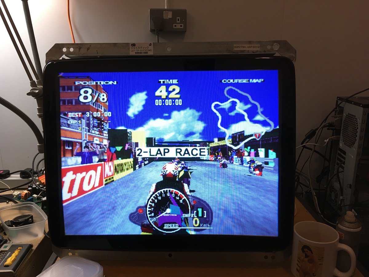
And a video of the new issue:
Basically I'de gone from everything being pretty messed up to now having much better rendering of the road and buidlings, particularly on every alternate 60hz frame. The other frames still had random polygon glitching going on.
I know from previous experience with these boards that the polygon memory appears to be double-buffered, so while the CPU and the 3D maths processors are writing to the polygon memory, the rendering system is reading polys previously written from the other memory bank.
There are six chips making up the polygon memory, two banks of three chips forming a 24-bit data buffer, so you've got low, medium and high data bytes.
The data bus is shared between each of the two banks, so IC7 data is connected IC8, IC9 to IC10, IC11 to IC12 etc.
If the polygons are fine on one set of frames but broken on the other then either one bank (IC8, IC10, IC12) or the other (IC7, IC9, IC11) will have one or more bad ram chips.

Now you can either replace them all with fresh new chips, or if you're like me you can investigate further and try to find the culprit.
So far I've found I can sometimes narrow down the approximate area where a faulty memory chip may be, this doesn't work in all cases but I've found it to be successful in the boards I've done.
I'll take a fine tip like some tweezers, connect them via a wire to ground and use it to short the data lines in turn on the 24bit polygon memory and watch the effect on the rendering to see if I can stabilise the glitching of the polys.
It seems that when these memory chips fail, it'll take down one or more databus lines which then start spurting out random noise, and if the databus line is grounded to a known state (ie. zero volts / '0' bit) then the polygoniser no longer sees random noise and the polygons become stable, they are still a corrupted mess because of one bit being locked to '0' but at least they're not moving erratically over time.
Here's a video of what I mean, bear in mind that my phone camera isn't recording at the 60hz refresh rate that the model 2 board is displaying at, hence it's recorded odd frames (30hz) for half a second, and then sees the even frames for the other half a second and flip-flops between the two states.
This does kind of help though, you can see periods where the polys are corrupt but stable, and moments where they are randomly glitching. This is where I'm grounding each data bit in turn, some stabilise the corruption, others make no difference to the randomising.
Finding stable polygons by grounding ram databus pins:
So from this, I found that shorting any of the pins on the medium and high memory chip data busses made no difference to the randomising, whereas if I ground the D7 line on IC7 & IC8 then the polys would settle down.
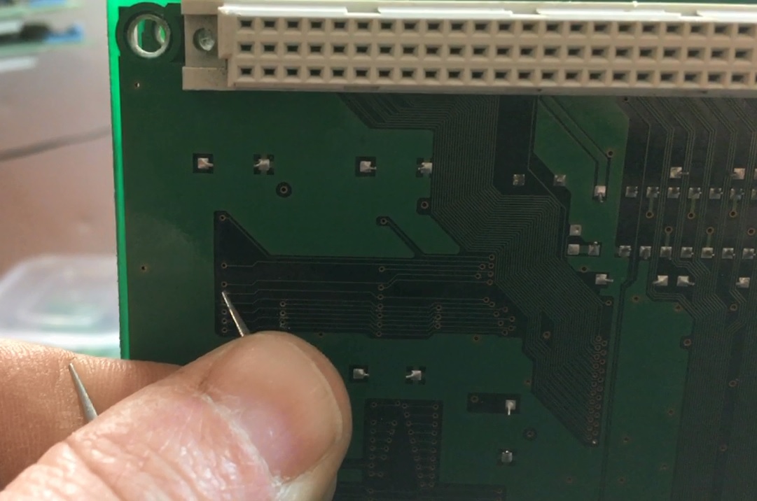
Shorting D7 on IC8 from the via on the back side of the pcb while it is running:
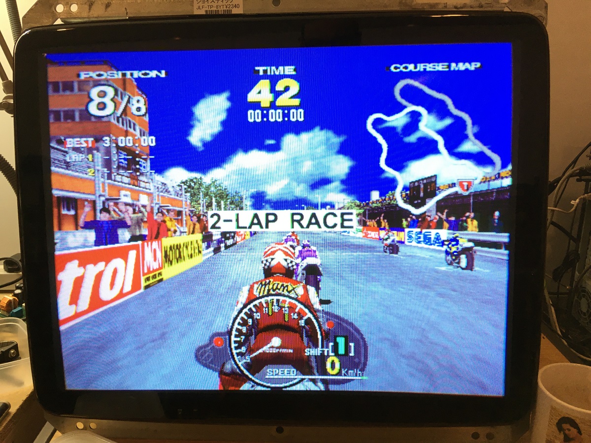
I took two known working ram chips from my spares collection and replaced IC7 & IC8 and bingo, all corruption fixed!
Now it's likely that only one of those chips (IC7 & IC8) is faulty, I could test them on a test jig I've made for these chips but I'll do that at a later stage and add any known working chip back to my spares.
But for now I was happy that it was working again.
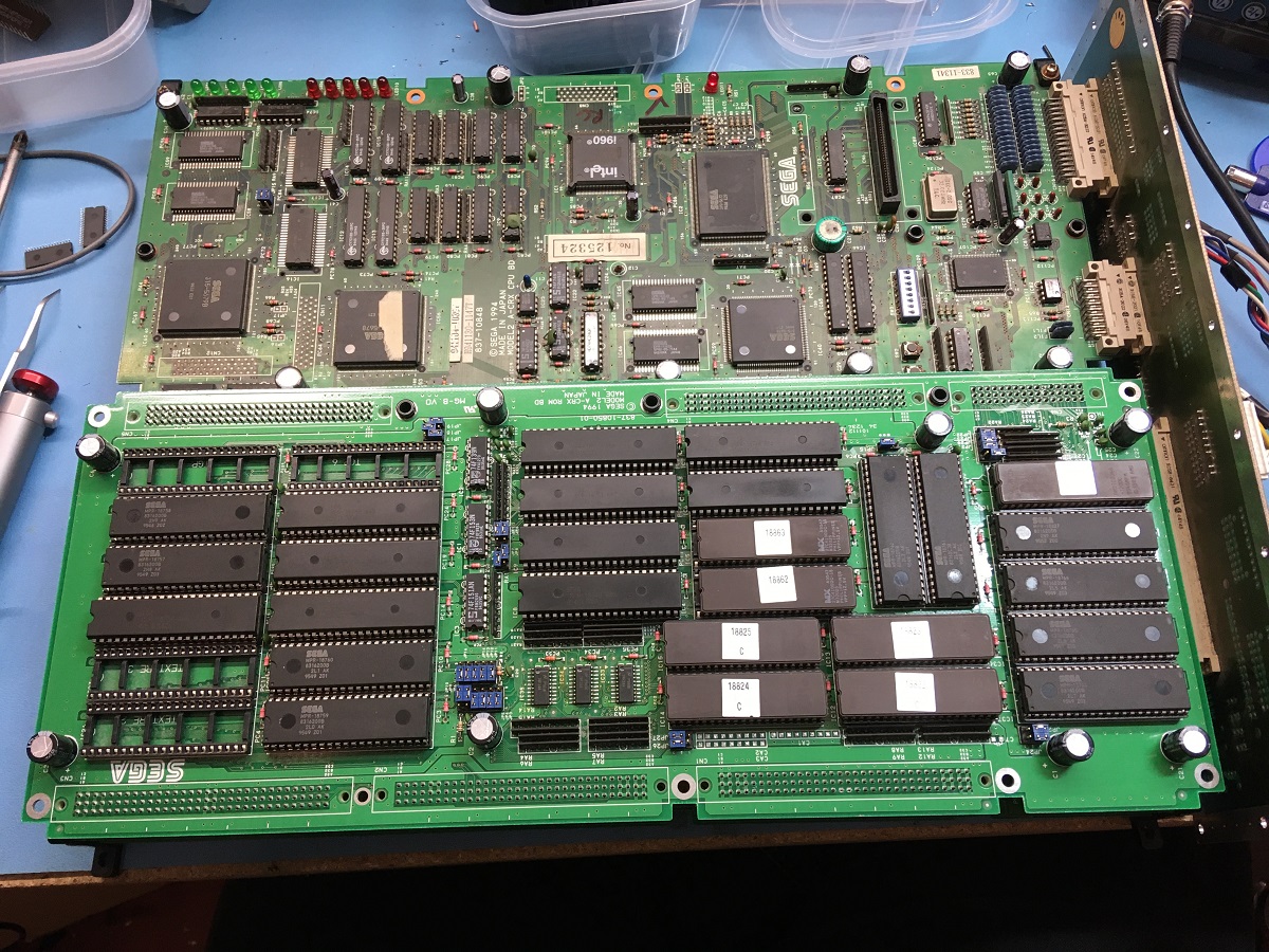
I then took this moment to give the rom board a good wash as it was a little bit filthy, I also noticed a couple of electrolytic capacitors had been broken off and some just came off in my fingers when giving them a gentle tug, so I recapped it as well.

And all back together:
Manx TT repaired:
Now while debugging these particular graphical glitches it's pretty difficult to do it while the game is running and you're getting new scenes or 2D frontends getting in your way.
I found that I could handily pause the game by crashing the CPU, preventing it from updating the 3D scene, but leaving the last two frames of scenery in the polygon memory so the 3D rasteriser hardware will happily keep rendering the same picture. That makes it a lot easier to trace faults around the board, either polygon, texture mapping or palette errors, caused by either bad chips or dry joints.
It's probably not wise to do this, I can't see it causing a huge amount of damage but I'de urge caution and not to do it often. Certainly I'm not taking any responsibility for anyone killing their CPU board!
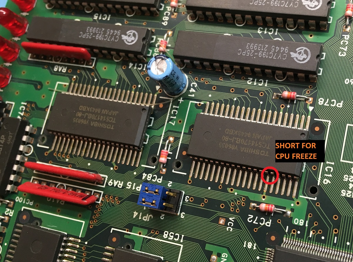
I've found that by shorting one of the data lines on the main CPU memory chips is usually a good way to crash the CPU, and crucially leave a 3D scene rendering. There's a lot of places a short like this will crash the CPU, but a lot will leave you with a blank screen, or just with 2D layers being rendered.
I basically take my tweezers and short pins 35 & 36 together, so grounding D13 on IC16 on the CPU board.

And here's a video of me performing said operation:
Pausing Model 2 video by crashing the CPU:
There's some other repair logs and info I still need to type up, I'll get it all rounded up in a repair guide someday I promise.
Hope that helps!
Steve.
lix2020-03-22 17:04:02
I got this Model 2A board recently from MysticMonk and put it on the repair bench for a look. The board stack was sold as faulty with graphic clitches and sure enough there were polygons with their points flying everywhere.
The graphics board looked pretty clean and had zero sign of repair which for me is quite uncommon, there are usually signs of reflowing or chip replacement or even factory issued repairs with patch wires fixing broken traces.
No signs of dust collecting around the polygon memory ram chips, no signs of the board having been cleaned. Maybe it was kept in a very clean environment, or had died pretty early in life and had been shelved all this time.
So the first thing I did in this area was to use an oscilloscope to probe all the address, data bus and control lines to see what the activity is like on all the memory chips and find anything obviously wrong.
Here's the pinout of the polygon ram chips (TC518128 on this particular board).
Pretty quickly I found that address line A13 (pin 28) which is applied to all six chips seemed to be stuck low constantly, it wasn't at completely ground potential of zero volts, it appeared to be around 0.2v and also seemed to have a bump of noise that bought it up to 0.5v every start of the 60hz video picture redraw.
I checked A13 with a multimeter to see if had continuity with ground but from seeing the slightly noisy signal I'de guessed correctly that it wasn't shorted to ground and was either being pulled low by a faulty ram chip or wasn't being driven properly by what I assume is the polygon memory management chip nearby which is IC1, a Sega custom chip numbered 315-5644 which has the markings of a Fujitsu manufactured chip (specifically the font used on the numbers).
I decided to take the plunge and replace this custom chip using one that I'de got from my spares board that has different issues.
So I desoldered the possibly faulty IC1:
And grabbed this one from another board:
Now fitted:
Powered the board up with the custom chip replaced and noticed an immediate improvement, but not a complete fix so some other problem was still occurring:
And a video of the new issue:
Basically I'de gone from everything being pretty messed up to now having much better rendering of the road and buidlings, particularly on every alternate 60hz frame. The other frames still had random polygon glitching going on.
I know from previous experience with these boards that the polygon memory appears to be double-buffered, so while the CPU and the 3D maths processors are writing to the polygon memory, the rendering system is reading polys previously written from the other memory bank.
There are six chips making up the polygon memory, two banks of three chips forming a 24-bit data buffer, so you've got low, medium and high data bytes.
The data bus is shared between each of the two banks, so IC7 data is connected IC8, IC9 to IC10, IC11 to IC12 etc.
If the polygons are fine on one set of frames but broken on the other then either one bank (IC8, IC10, IC12) or the other (IC7, IC9, IC11) will have one or more bad ram chips.
Now you can either replace them all with fresh new chips, or if you're like me you can investigate further and try to find the culprit.
So far I've found I can sometimes narrow down the approximate area where a faulty memory chip may be, this doesn't work in all cases but I've found it to be successful in the boards I've done.
I'll take a fine tip like some tweezers, connect them via a wire to ground and use it to short the data lines in turn on the 24bit polygon memory and watch the effect on the rendering to see if I can stabilise the glitching of the polys.
It seems that when these memory chips fail, it'll take down one or more databus lines which then start spurting out random noise, and if the databus line is grounded to a known state (ie. zero volts / '0' bit) then the polygoniser no longer sees random noise and the polygons become stable, they are still a corrupted mess because of one bit being locked to '0' but at least they're not moving erratically over time.
Here's a video of what I mean, bear in mind that my phone camera isn't recording at the 60hz refresh rate that the model 2 board is displaying at, hence it's recorded odd frames (30hz) for half a second, and then sees the even frames for the other half a second and flip-flops between the two states.
This does kind of help though, you can see periods where the polys are corrupt but stable, and moments where they are randomly glitching. This is where I'm grounding each data bit in turn, some stabilise the corruption, others make no difference to the randomising.
Finding stable polygons by grounding ram databus pins:
So from this, I found that shorting any of the pins on the medium and high memory chip data busses made no difference to the randomising, whereas if I ground the D7 line on IC7 & IC8 then the polys would settle down.
Shorting D7 on IC8 from the via on the back side of the pcb while it is running:
I took two known working ram chips from my spares collection and replaced IC7 & IC8 and bingo, all corruption fixed!
Now it's likely that only one of those chips (IC7 & IC8) is faulty, I could test them on a test jig I've made for these chips but I'll do that at a later stage and add any known working chip back to my spares.
But for now I was happy that it was working again.
I then took this moment to give the rom board a good wash as it was a little bit filthy, I also noticed a couple of electrolytic capacitors had been broken off and some just came off in my fingers when giving them a gentle tug, so I recapped it as well.
And all back together:
Manx TT repaired:
Now while debugging these particular graphical glitches it's pretty difficult to do it while the game is running and you're getting new scenes or 2D frontends getting in your way.
I found that I could handily pause the game by crashing the CPU, preventing it from updating the 3D scene, but leaving the last two frames of scenery in the polygon memory so the 3D rasteriser hardware will happily keep rendering the same picture. That makes it a lot easier to trace faults around the board, either polygon, texture mapping or palette errors, caused by either bad chips or dry joints.
It's probably not wise to do this, I can't see it causing a huge amount of damage but I'de urge caution and not to do it often. Certainly I'm not taking any responsibility for anyone killing their CPU board!
I've found that by shorting one of the data lines on the main CPU memory chips is usually a good way to crash the CPU, and crucially leave a 3D scene rendering. There's a lot of places a short like this will crash the CPU, but a lot will leave you with a blank screen, or just with 2D layers being rendered.
I basically take my tweezers and short pins 35 & 36 together, so grounding D13 on IC16 on the CPU board.
And here's a video of me performing said operation:
Pausing Model 2 video by crashing the CPU:
There's some other repair logs and info I still need to type up, I'll get it all rounded up in a repair guide someday I promise.
Hope that helps!
Steve.
lix2020-03-22 17:04:02
")

