Space Battle - Transformer Question

biglouie

Active member
vacBacker
Credits
83CR
Hey all..

I wonder if someone can help/guide me..

I bought a Space Battle cocktail to restore.

pic_of_cab.jpg


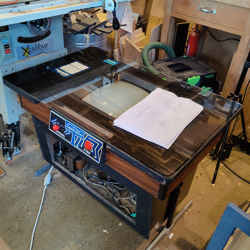
Just garbage on the screen for the time being, but it looks to have "some" original bits, so thought I better start at the power. I haven't really worked with a transformer like this before and AC, so wanted to ask a question.

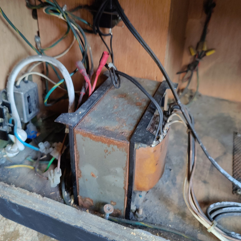
The transformer looks like this...The red bits are the selector for mains power. Its set to 240v at the moment.
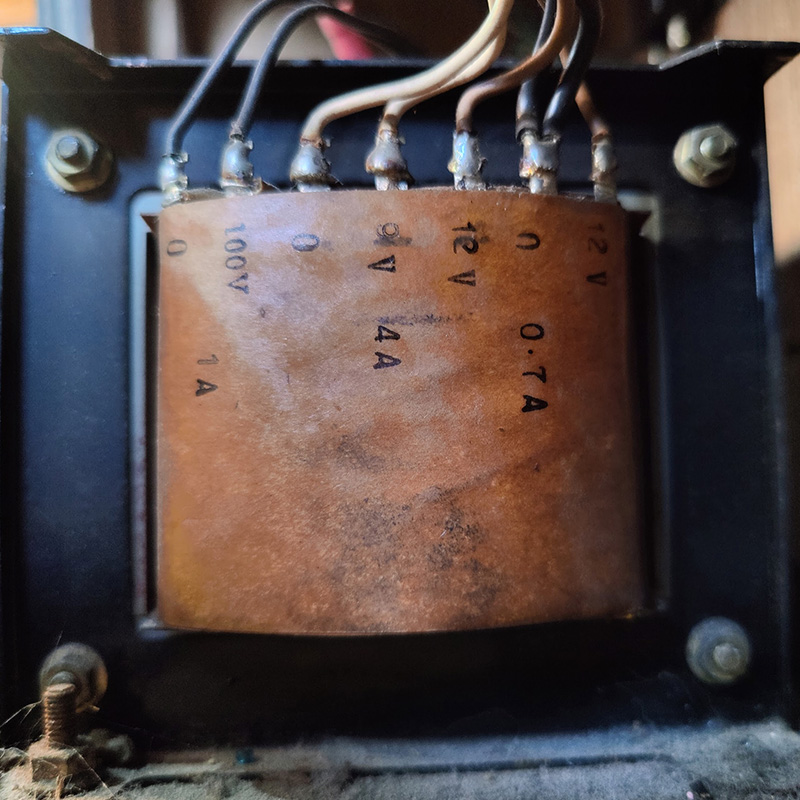
pic_of_trans&


And a closer view

pic_of_tra_ns&


If I want to test this with a meter...?

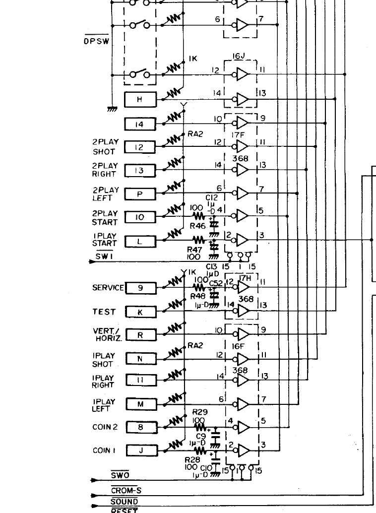
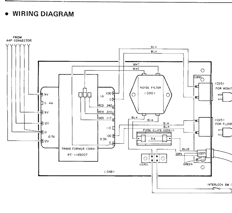
It's slightly different to the schematics I have. I assume the schems are for the upright and not cocktail I think. I don't have a lamp, for example..

So I am assuming that my transformer is (from the picture above)

0 and 100 - They go to the monitor.

0 and 9v - 9v AC

12v and 0 - 12v AC

0 and 12v - 12v AC

I am assuming on my transformer, that the 0 is shared by thr two 12v outputs either side of it (on the right of my picture)

trans&


biglouie2021-12-22 10:35:25
 

biglouie

Active member
vacBacker
Credits
83CR
Due to a kind off forum message, I have an update

I've tested with AC on the Multimeter...

0-100 - 102v

0-9v - 9.3v

0-12v - 12.4v

0-12v - 12.5v

So AC out of transformer appears good.

Testing the edge connector for AC next and 5v on the board.

The 5v appears to come from the 9v AC being rectified and smoothed as below..

I need to work out what the F, C3 and D4 boxes refer to, just curious.

5v_rectified.jpg


biglouie2021-12-22 11:50:18
 

smarty

Ready Player One
vacBacker
Feedback
12 (100%)
Credits
1,289CR
Rob, the letters and numbers in boxes on the left of the diagram will be the edge connector fingers where the harness connects. One side will be labelled A-Z and the other 1-22 or similar depending on how many pins there are.

Put your Multi-meter across C49 (set to DC) this should tell you if you have 5V coming out of the rectifier and regulation section.

smarty2021-12-22 11:57:02
 

biglouie

Active member
vacBacker
Credits
83CR
Thanks Smarty...

Let confusion reign! This schem has no letters on this bit, but DOES on the diagrams

Screenshot_2021-12-22_at_12.19.13.png


and the diagrams.. The joys :)

Screenshot_2021-12-22_at_12.25.29.png


I'm off to test 5v!
 

biglouie

Active member
vacBacker
Credits
83CR
Sooo... had a quick look at C49,50,51 with zi meter..

these bad boys..

c49.jpg


All 3 read 9.7v dc. Had to get at them from the back obvs..

I don't understand why 16v caps. I need to go and read up on capacitors again.. they smooth the output from the rectifier? they dont look bloated at least.
 

Lurch666

Active member
Feedback
21 (100%)
Credits
4,142CR
RE: the conflict between the diagram and schematics:

If you note on the schematics (bottom picture) player 1 right is pin 11.

If you count from the bottom up but only count the odd numbered pins (wiring side) of the diagram (upper picture) player 1 right is the 11th pin.

Lurch6662021-12-22 13:12:52
 

Phils Arcade

Senior Member
vacBacker
Feedback
9 (100%)
Credits
1,387CR
The 16v is the max voltage that they'll work at, you can put higher and that would still do, It's the cap value you need to go by.

The caps don't have to bulge in order for them to be bad. If still original, and they look like it, the electrolyte can dry out, thus not doing their job. If used as smoothing an AC voltage, or rectified circuit, they can allow the AC cycle to pass and cause all sorts of issues with your board.
 

biglouie

Active member
vacBacker
Credits
83CR
I'll try and find the output cap shortly and measure that. It seems that the schematic might have a misprint around this area. Seems to restate c49,50,51 twice... And that cannae be..

Hunting for the outward cap... Those 3 seem to be on the way into the BR..
 

biglouie

Active member
vacBacker
Credits
83CR
Quick update incase anyone following...

Checked the outbound cap of the BR. 5v which is good. I "feel" like the power side of things might be ok?

The edge connector shows the 9v at 5v though... 12v is steady at the edge at 12v. So not sure if something to investigate there, or maybe thats just 9v going under load with board plugged in. Maybe I should check without board.

I've pulled all the ROMs, burned the code off and saved it down, all read fine, or so it seems.

When it's turned on, it makes an unfun squealing sound. Sometimes get star field and garbage. Sometimes just garbage.

garbage_screen.jpg
 

Lurch666

Active member
Feedback
21 (100%)
Credits
4,142CR
That's the PCB failing to properly run the software.

I'm working on bootleg mooncrestas at the moment and since the starfield is generated by hardware it can appear even when the CPU isn't running the software.

If the CPU is in a socket try replacing it. A picture of the PCB would help then we can suggest which components could be at fault.
 

biglouie

Active member
vacBacker
Credits
83CR
Few bits and bobs.

First a picture of the board as requested Lurch.

I'm told it's like a Galaxian. I've been watching Galaxian repair videos, I would say it is much like a Galaxian board from what I am seeing.

IMG-20211221-WA0034.jpeg


I haven't got a D780C (Z80 versus Z80a) to swap in.

I've got all the code off the 16k ROMs, need to get the d2364c to read in my burner. Working on that now

IMG_20211222_144908.jpg


All power seems good. Caps seem ok with 5v pretty strong.

Clocks seem good and I've checked the LS161s around the horiz and vert outputs, seems ok. I haven't had it on a scope though.

Cant find any obvious "dead" ICs, with random mooching about the board with probe.

I might see if some of the socketed stuff checks out ok in a tester as thats fairly easy.

I havent found any chips of anything in the cabinet itself.

I did find a ribbon cable, which is likely to meant to be connected to another sound board according to schematics. I do not have said board.

RESET starts lo and goes hi and remains.

Star field is sometimes there, sometimes not on power cycle.

Cant find the game in Mame.. Anyone got a working board that looks like this for Space Battle?

Chap I bought from said "it was working, then it wasn't and I couldn't be bothered with it" Sounds familiar! :)

biglouie2021-12-26 14:03:24
 

Lurch666

Active member
Feedback
21 (100%)
Credits
4,142CR
(EDIT:Noticed you thought the 2364 was rom but it's a ram chip so it's not going to read as a rom.)

You have a 2364 ram chip socketed at K4 that might have failed.

You also have a set of 2114 ram at 6K-9K that might or might not affect the software running.

Plus of course testing/replacing the Z80.

Do you have any other PCBs that you could grab a Z80 from (and maybe a2364 or equivalent).

Would also check the legs of ALL your eproms and socketed chips since tarnish or rust can affect connections.

And have a close look at the underside of the PCB to see if any protruding pins are touching or any tracks have been gouged.

Lurch6662021-12-26 15:01:42
 

biglouie

Active member
vacBacker
Credits
83CR
inspection of underside seems ok. Nothing obvious
Ive got Z80a on the way and 2364. I didn't have anything in other boards.

We can give that a go and see where that gets me.

Power seems to check out.

No clue how to test 2114. If it involves sticking the scope on it and checking phasing of write and read cycles, then it might be a "nerd-out too far" for me.. I guess seeing when CS and WE combine.. But man, that stuff blows my mind.. https://hardware.speccy.org/datasheet/2114.pdf

The big old sand resistor around the power area gets hot as hell, as does the heat sink on the BR. Given all the ICs and small electrolytic caps etc around there, I wonder if all that heat has caused failures down there. If its been left on for hours one time...then... I dont know. I need to refresh my brain on reading the scope again :)

biglouie2021-12-27 14:13:25
 

Lurch666

Active member
Feedback
21 (100%)
Credits
4,142CR
With the 2114 check for activity on all the pins except for GND (pin 9) and +5V (pin 18) obviously.

But that only shows data in and out plus select signals. You can't verify if the chip is holding the correct data without either swapping out for a known good chip or using other hardware that can check the chip while it's still in the PCB although piggybacking a good 2114 can show faults sometimes.

For now don't worry about stuff that's not socketed-check the CPU and 2364 ram first and then go from there if you need to.
 

biglouie

Active member
vacBacker
Credits
83CR
2114 update. All show a flavour of the same shiznit on the scope (Data probe seems to have died)

Everything is pulsing except ones below.. 8 is important as that control CS.?

1 - lo

8 - hi

9 - lo (gnd)

18 - Hi (5v)

Screenshot_2021-12-27_at_18.45.32.png


Screenshot_2021-12-27_at_18.48.19.png


Curious, the diagram below.. does it mean PIN8 on the EPROMS (right) is controlled by pin5 on 4F?

Screenshot_2021-12-27_at_19.07.28.png


---snip from datasheet---

Functional Description:
Two pins control the operation of the NTE2114. Chip Select (CS) enables write and read operations
and controls TRI–STATING of the data–output buffer. Write Enable (WE) chooses between READ
and WRITE modes and also controls output TRI–STATING. The truth table details the states produced by combinations of the CS and WE controls.
During READ–cycle timing, WE is kept high. Independent of CS, any change in address code causes
new data to be fetched and brought to the output buffer. CS must be low, however, for the output buffer
to be enabled and transfer the data to the output pin.

Address access time, tA, is the time required for an address change to produce new data at the output
pin, assuming CS has enabled the output buffer prior to data arrival. Chip Select–to–output delay,
tCO, is the time required for CS to enable the output buffer and transfer previously fetched data to the
output–pin. Operation with CS continuously held low is permissible.
Writing occurs only during the time both CS and WE are low.

Minimum write pulse width, tWP, refers
to this simultaneous low region. Data set–up and hold times are measured with respect to whichever
control first rises. Successive write operations may be performed with CS continuously held low. WE
then is used to terminate WRITE between address changes.

Alternatively, WE may be held low for
successive WRITES and CS used for WRITE interruption between address change.
In any event, either WE or CS (or both) must be high during address transitions to prevent erroneous
WRITE

biglouie2021-12-27 19:09:51
 

Lurch666

Active member
Feedback
21 (100%)
Credits
4,142CR
When you say ALL 2114s are showing the same do you mean just the four at 6K,7K,8K and 9K or does that also include the ones at 4D and 5D?

Anyway pin 1 being stuck looks like a possible address problem and pin 8 being high all the time means the chips are never going to be selected BUT this just might be a symptom of a bad CPU or the other ram being bad so until you can eliminate those don't worry too much about the 2114s as they don't appear to be in sockets.
 

biglouie

Active member
vacBacker
Credits
83CR
2114s on the K line, yup.. Didnt do the others at D. Will have a quick look tomorrow.

We await CPUs and new ram to close that off a bit. I might pop down to storage and see if I've got a Z80a down there in a board, rather than wait.
 

PaulSwan

ZZZ
Feedback
1 (100%)
Credits
1,117CR
If this was a Galaxian, you'd ordinarily get a boot to a RAM failure message if the RAM was bad. It doesn't look like your board is getting that far, possibly suggesting the CPU isn't able to run properly or fetch instructions from the ROMS. You could try a new Z80.

The most expedient way forward maybe to take a trip to someone with a Fluke 9010 or one of the other in circuit CPU emulation test tools and an oscilloscope. Those would tell you in minutes if the ROMS & RAMs are all good and allow you to see the signals to fault find.

Fingers crossed it's a simple case of a bad CPU ;)
 

biglouie

Active member
vacBacker
Credits
83CR
Fingers crossed Paul!

CPUs on the way. I would LOVE to spend some time with someone who has a Fluke 9010, to see it all working. (I watch FAR too many pcb repair videos and they are often in there!)

This is extra tricky for me, as I don't have a test rig on a bench that has 12v and 9v ac, I'd need to build something. So I've moved the scope and wotnot to the cocktail machine :)
 
Top