Hi everyone,
I have an odd issue with a Stern Super Cobra PCB. Up is constantly on. I've discovered the problem but I'm not sure how to correct it. The schematics show A9 is up and is attach to a 0.1uf capacitor and a 220 ohm resistor.

Unfortunately, the 220 ohm resistor doesn't exist and the trace goes straight into a 0.1uf capacitor. I've changed the capacitor, to no avail. The resistance across the capacitor is about 10Mega ohms before and after I changed it. All other control inputs have a resistor attached to +5V to keep the signal high. When I place the logic probe on the trace in front of (and in series with) the 0.1uf capacitor the signal is driven above low and the up is turned off. Only problem is, once I press up on the pad the signal is driven low and stays low (so it's up on constant again. Place the logic probe on it and it goes away again. It's an odd one and one I hope someone has come across before.
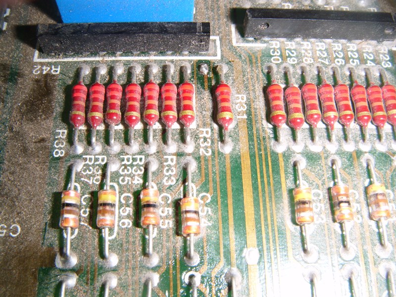
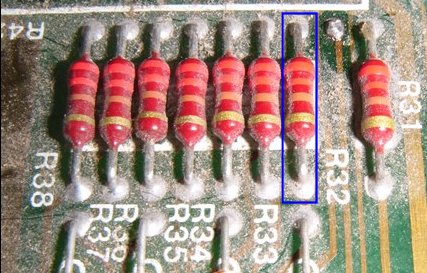
The resistor should be at R32 and you can see where I changed the 0.1uf capacitor for a mylar one. When I touch the soldering eye at R32 the issue disappears as the circuit is driven above low but it never reaches high. Don't want to just connect it to a high signal, thought I'd ask first.

Thanks for any help.
I have an odd issue with a Stern Super Cobra PCB. Up is constantly on. I've discovered the problem but I'm not sure how to correct it. The schematics show A9 is up and is attach to a 0.1uf capacitor and a 220 ohm resistor.
Unfortunately, the 220 ohm resistor doesn't exist and the trace goes straight into a 0.1uf capacitor. I've changed the capacitor, to no avail. The resistance across the capacitor is about 10Mega ohms before and after I changed it. All other control inputs have a resistor attached to +5V to keep the signal high. When I place the logic probe on the trace in front of (and in series with) the 0.1uf capacitor the signal is driven above low and the up is turned off. Only problem is, once I press up on the pad the signal is driven low and stays low (so it's up on constant again. Place the logic probe on it and it goes away again. It's an odd one and one I hope someone has come across before.
The resistor should be at R32 and you can see where I changed the 0.1uf capacitor for a mylar one. When I touch the soldering eye at R32 the issue disappears as the circuit is driven above low but it never reaches high. Don't want to just connect it to a high signal, thought I'd ask first.
Thanks for any help.