Hey all, so far I had some help in this wanted thread and I thought move it here.
So I am still struggling to get the game to link, I am attempted wiring it without the relay board and I tried to understand the schematics that I seen so far.
I found some documents online that gave me some idea of how it links up.
So I tried this , RINGOUT >> RINGINA which then goes to pin44 RING and done the same with the other second player board.
RINGINK I see is the opposite ground side to opto, so I just linked that to RINGINK (and on Final Lap 3 pinout it would be called RING IN C)
SWSWITCH I think is the Relay switch on the board, why did the use relays ? I presume for multiple machines so I ignored this.
I have RANK B and RANK B in the setups and GRID No 1 and 2
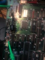
I still get ERROR and I scoped both and happy that the signal is getting to the C139 chip
HAVE I DONE THIS RIGHT? Any help appricated as I dont have the cabinet wiring here and I am thinking its the cabinet wiring but need to rule out on the bench (floor) what I am doing wrong?


So I am still struggling to get the game to link, I am attempted wiring it without the relay board and I tried to understand the schematics that I seen so far.
I found some documents online that gave me some idea of how it links up.
So I tried this , RINGOUT >> RINGINA which then goes to pin44 RING and done the same with the other second player board.
RINGINK I see is the opposite ground side to opto, so I just linked that to RINGINK (and on Final Lap 3 pinout it would be called RING IN C)
SWSWITCH I think is the Relay switch on the board, why did the use relays ? I presume for multiple machines so I ignored this.
I have RANK B and RANK B in the setups and GRID No 1 and 2
I still get ERROR and I scoped both and happy that the signal is getting to the C139 chip
HAVE I DONE THIS RIGHT? Any help appricated as I dont have the cabinet wiring here and I am thinking its the cabinet wiring but need to rule out on the bench (floor) what I am doing wrong?