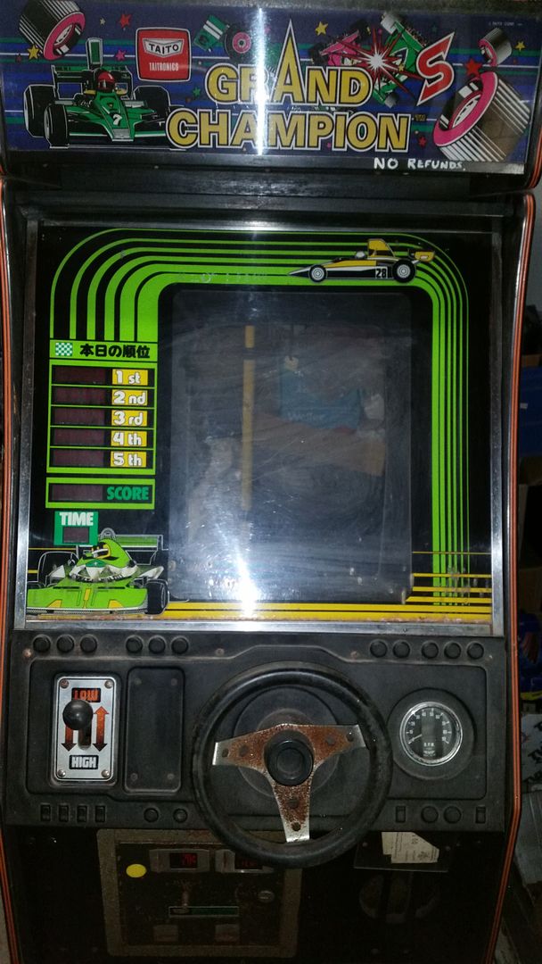
I decided to see if I can get my Taito Grand Champion PCB working today.
The pinout wasn't available so I worked it out from the schematics and uploaded it to KLOV.


Manual here:
https://drive.google.com/open?id=0B0kAwpS2NEYzaE51SkpqX3FEb00
I made up a Jamma adapter so I could work on it on the test bench.
I have two boardsets, one was the original from the cab and looks like someone has poured a can of Coke over it.
The other is one I bought untested from The Arcade Boneyard ages ago and when I plugged it in there was nothing on screen.
The boards and cab resto were put on hold for the last 12 months or so.
So my test procedure when there is no activity is to start at the clock and move out from there.
After a bit of probing around I could see that the 74LS161 at 4L was dead on all outputs.
It was removed and socketed and new chip installed.
I now had life coming from pins 11,12,13,14.
Still no image on screen.
Further probing down the line and I found weak signals coming from the 74LS161 at 5L.
It too was socketed and replaced and there was a flash of image when the board was powered up.
The out put at pin8 on the 74LS74 at 7K looked weak as well so it was socketed and replaced.


When the board was powered back up again I got this image on screen but it kept resetting over and over.

I started thinking, okay Power On Reset...
Went back to the schematic and found pin10 on the 74LS00 at 15E was pulsing.

When I tied pin6 of the 74LS393 at 16F low, the game booted up and played as normal.
https://www.youtube.com/watch?v=FFGNqjoKWJk


That's about as far as I got today.
I'll plug it in the cab tomorrow and see how it goes.
Kaizen0882017-04-01 00:48:49


