TRON Cocktail Spinner Fault

Jodo

Boy is this a machine!
Staff member
vacBacker
Feedback
15 (100%)
Credits
607CR
Hi all,

Pushing this up here as a work in progress as I find it interesting. I'm pretty confident now it can be fixed too and who knows, it may help somebody in the future with which components to check / swap out in their troubleshooting
smiley1.gif


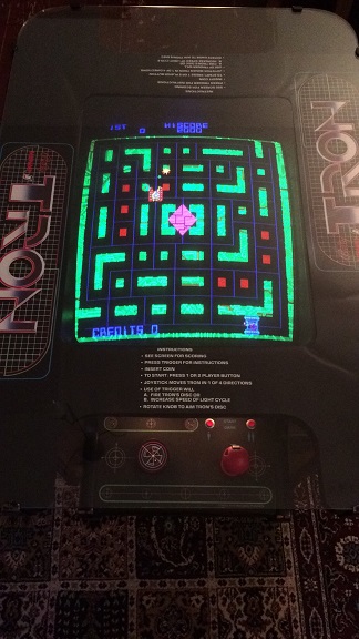
The patient: TRON Cocktail Cabinet
Status: Working with fault
Notes: Has had the switching PSU conversion performed

Fault(s) Primary: Erratic spinner output - TRON's arm jumps in random directions on Player 1 and Player 2 and only moves in one direction

Fault(s) Secondary: 'UP' on Player 1 joystick not registering. Very loud hum in attract mode (hum not present in game)

Background:

I was very fortunate to pick this TRON Cocktail at a superb price from another member on here. I bought it as working with a known fault, in that the spinner 'jumped', making gameplay difficult. I was more than informed this was the case and the fault was reflected in the price we agreed on. Upon receipt the cab was exactly as described, specifically:

  • In both test mode and in game, TRON's arm jumped to random points when the spinner was turned and in fact only rotated clockwise; even when the spinner was turned anti-clockwise
  • The attract mode played with audio interference, which manifested itself as a loud hum; this lasted until a credit was added and the game started, whereupon the hum disappeared and normal volume was heard
Tron_Cocktail_Web_Sized.JPG


Initial Fault-finding:


  • Visible inspection of all connectors and plugs for connectivity; located 1 x pin in P1 CP joystick plug half out (probably knocked in transport) Reinserted pin - 'UP' direction fixed
    smiley32.gif
  • Metered 4 x 5v lines at edge connector - All good
  • Metered 12v at edge connector, at the spinner CP plug and at the spinner PCB - All good
  • Metered 5v across PCB - Good
  • Metered continuity from all plugs / pins in loom and at PCB (soul destroying but necssary) - All good
  • Metered all GND connections for continuity and shiz & giggles - All good
Initally I thought that the issue with the erratic arm movement was related to the fairly common fault of a broken spinner optical encoder PCB and I ordered 2 reproduction replacements from the US.

http://www.twistywristarcade.com/bally-midway/637-reproduction-tron-optical-encoder-pcb.html
  • Removed P1 control panel and spinner PCB assay and replaced with reproduction spinner optical encoder PCB; reinstalled in cabinet - spinner fault unaffected, remains
So, having been denied the legendary and elusive 'easy fix', I began to look more closely at the cab internals. It could possibly be that the black switcher has gone? I had no way of determining how long the switcher had been in the cab and as I had a few spare it would be easy to eliminate that as a possible culprit.

  • Removed switching PSU, replaced with brand new switcher; reinstalled in cabinet - spinner fault unaffected, remains
Whilst swapping out the switcher, I noticed that the transformers in the base of the cocktail had been swapped out for new, modern equivalents. The cab had come with a heavy box marked 'Very heavy'
smiley2.gif
...which contained the orginal transformers and cab power assay contents; prime amongst these components was the original power supply PCB that is discarded when the switching PSU conversion is performed. I recall the seller saying that the transformers and power supply PCB were essentially included as spares and that he suspected one of them was causing the cab to blow fuses.

I decided that not only did I 'like a challenge' but that perhaps Neil / Mitchell Gant would also like a challenge, so I immediately decided that all of the new modern transformers and the switching conversion were to be removed and all of the old original parts would go back into the cab. It is at this point that the seller, who will likely read this, will go ballistic. I'm staring at my phone right now and I'm telling you, there will be a message of some sort and possibly some swear words. It must have taken hours to rewire and refit the cab and I'm going to rip it all out
smiley4.gif


All I can say is........'Have faith'
smiley2.gif


I phone Neil, who unsurprising, is in the process of collapsing an unstable worm hole in his basement with his mate 'Dave'....

"Neil! It's TRON's arm! It's all OVER the place. You've never seen anything like it!"

"Bring the power PCB and all of the old transformers over! I'll have a look just as soon as I've finished collapsing this very unstable worm hole I've created!"

I drop the (very) heavy box over at Neil's workshop. He looks somewhat dishevelled and is wearing a white lab coat with a
smiley34.gif
symbol on the back.

"Everything OK? What are you up to here?"

"Oh, nothing, just a little.......weather experiment..."

Power Supply and Transformer Test

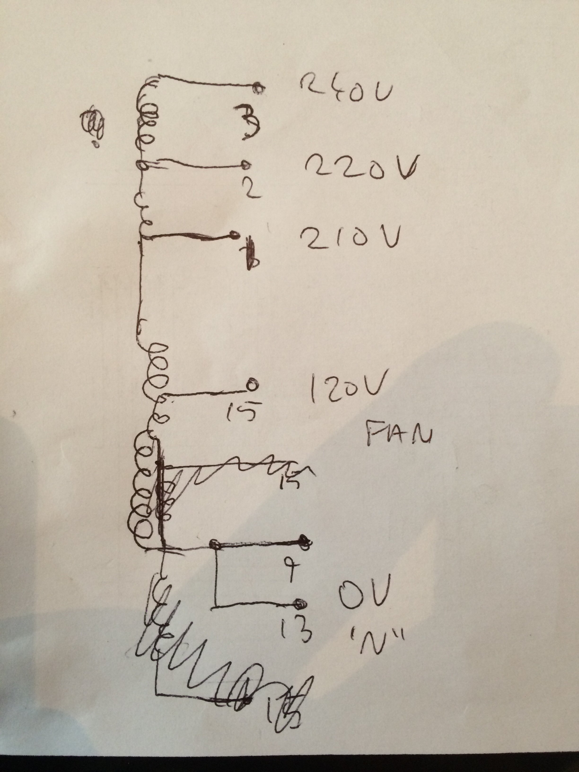
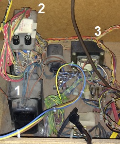
Over the course of the next 2 weeks, Neil has the original transformers and the power supply PCB on his test bench:

Tronpowerassay.jpg
Tronpowerassay2.jpg

  • (1) Large Main Transformer #1 - Tested Bad: current draw / power output way over factory / normal (It was likely this that was blowing the fuses)
  • (2) Filter Assembly - Tested Good
  • (3) Smaller Transformer - Tested Good
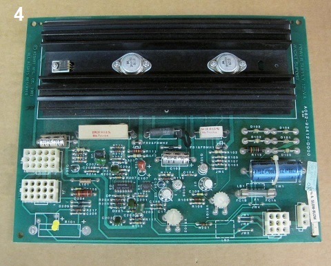
  • (4) Power Supply PCB - Tested Bad: 5v and 12v incorrect / 5v won't adjust

Fortunately I have a complete spare UK 240v TRON power brick setup and so I am able to supply Neil with a replacement
Large Main Transformer. We are not so lucky with the Power Supply PCB; probably the only part I don't have a spare of. It will need to be rebuilt if we are to continue with our plan of putting the cab back to factory.

  • (1) Large Main Transformer #2 - Tested Good
  • (4) Power Supply PCB partially rebuilt; new 5v adjust pot added - Tested Good under load

Converted cab back to factory:

  • Unplugged loom from and removed switching PSU, conversion PCB and all associated wiring
  • Removed power board from base of cab; detached all loom plugs, GND and mains power cable wiring, (desoldered where necessary)
  • Unscrewed transformers and filter components from board
  • **Board now bare**
  • Installed factory transformers, filter assembly, line / noise filter; GND connections, mains power cable; soldered where necessary
  • Installed rebuilt power supply PCB into holder inside cab
  • Reconnected all loom plugs
  • Realised one female plug and associated pins missing. Lost a week waiting for new pins to arrive
  • Hid from the seller
Switch on & Test:
  • Metered 4 x 5v lines at edge connector - A little low at 4.75v
  • Metered 12v at edge connector - Tested good
  • Tested game PCB in confirmed working TRON upright - Tested Good
  • Installed game PCB into TRON cocktail / power on - Game boots into attract mode; no 'hum' heard
    smiley32.gif

  • Game start - P1 and P2 controls tested - All joystick directions and both spinners work perfectly
    smiley20.gif

Unfortunately 48 hours later, the cab sounds start to distort, then gradually disappear or play at the wrong speed and then suddenly, the cab is dead and the game board refuses to boot at all.

To be continued......


Jodo2015-05-31 20:00:22
 

guddler

Busting vectors like it's 1982!
vacBacker
Feedback
10 (100%)
Credits
4,054CR
Thanks for writing this up...

Just so you know, the black switch mode supply was brand new and more or less unused so don't chuck it. If the game board is now refusing to boot, have you put the wire back into the loom that was removed? I think it's either the purple or the grey one and something to do with the reset line. Man my memory sucks. If that's back in then remove it again, your game will probably boot.

Tron will work down to about 4.3v with that wire removed. Much below that and you won't get any joy though. Leave the wire in and you won't get very low at all as the reset circuit will prevent the board from coming up.

Chances are though that it was just fluke that the power PCB worked for a while without being rebuilt.

I'm interested if you can document the process of rebuilding the power PCB. I need to do it to my cabaret and don't have the luxury of all the parts to shotgun it.
 

Jodo

Boy is this a machine!
Staff member
vacBacker
Feedback
15 (100%)
Credits
607CR
Hi Gudd,

Upon first power on following the installation of the original transformers, the game refused to boot. We plugged the purple reset wire back in and the game booted and played; initially fine but as per my write up above, started to deteriorate over 48 hours. Now the game won't boot with the purple reset wire in, or out sadly.

Regarding the rebuild of the Power Supply PCB, I'll invite Neil to the thread to summarise as I wasn't present at the time.

The next write up will reveal what Neil believes is the issue and (possibly) by then, whether it actually was AND if it's fixed! Exciting stuff
smiley1.gif
 

Mitchell Gant

Active member
vacBacker
Feedback
2 (100%)
Credits
884CR
We've made some progress on this tonight and although it's not fixed yet it looks very much like a silly wiring mistake on my part.
smiley18.gif


With the game pcb plugged in the regulator voltage would not adjust over about 4.5V, but unplugged i.e. no load and you had a lovely 5V or higher if you turned up the trimmer pot.

So the suspicion was obviously a bad regulator circuit component.The regulator needs two supply voltages, a 10V and a 20V input which regulate down to 5V and 12V respectively. Using a bench DC supply I found the regulator worked perfectly as long as the input voltages stayed above about 7V and 15V, so no fault found there. Any lower input and it showed the same problem that the cabinet was having.

Testing again in the cabinet with no game pcb plugged in showed a reasonable 9V and 15V inut to the regulator, but plugging the game in and those voltages dropped to 6V and 12V!! No wonder it can't supply 5V output from that!

After quite a bit of head scratching and measuring of transformer AC output voltages I was surprised to see even a small load of a car indicator lamp (found in boot of my car) was enough to drag the AC voltage down.

Finally I metered the mains AC inut voltage to the main transformer... 102V AC, ahh that would explain it! Amazing it gave enough output at all to run the game.

It looks like the schematic diagram for Tron, which shows the monitor isolation transformer having a single primary wired to a connector block that distributes 240V mains to the other power transformer and a fan, does not match the actual isolation transformer in the cabinet. The actual transformer appears to have different primary voltage tappings, and the power transformer has been wired to one of these tappings rather than directly to 240V AC.

Also not helpful is the Tron wiring of blue for lives and brown for neutrals to the fan transformers.
smiley5.gif


As for the switch mode supply causing the spinner problem, only thing I can think is some high frequency switcher noise getting through to the optos on the spinner. I suspect a different model/make of switching supply would not cause the problem.

So a few lessons here. Don't assume the manual/schematic is exactly what the cabinet is, or that wire colours are matching UK mains standards. And don't do house calls to other members cabinets in case you end up in the shower with them, holding a torch and a camera while they pass you their large tools. Again.
 

Jodo

Boy is this a machine!
Staff member
vacBacker
Feedback
15 (100%)
Credits
607CR
smiley4.gif
Thanks to Neil we now have hot running water in our shower again! Came to troubleshoot TRON, ended up fixing my shower
smiley36.gif


/Back on topic...

I want to pick up on a point that Neil makes:

"As for the switch mode supply causing the spinner problem, only thing I
can think is some high frequency switcher noise getting through to the
optos on the spinner. I suspect a different model/make of switching
supply would not cause the problem.
"

So the primary fault on the cab was caused by the switching PSU conversion. Interesting. More to follow!
 

Jodo

Boy is this a machine!
Staff member
vacBacker
Feedback
15 (100%)
Credits
607CR
You are in a room.

TRON Cocktail is here.

Neil is here.

What should I do?

> Play TRON Cocktail.

You cannot play TRON Cocktail, it's broken.

What should I do?

> Say Hi Neil

Neil nods politely.

What should I do?

> Ask Neil to fix TRON Cocktail

Neil cannot do that right now, he's fixing your shower.

What should I do?

> MAME TRON Cocktail

I'm sorry I don't understand that command.

What should I do?


The above scenario will for many bring back happy memories of 8-bit adventure gaming. I hope it does; it did for me. The truth is that Neil did help; to the tune of coming around to my house no less than 3 times all told.

When I last updated this thread we were both essentially looking at a dead cab. I have on more than one occasion during this past few weeks said the words that no collector ever wants to utter...

"If we can't get it working this time, I think it's time to call it a day and offer the cab up for sale.."

Neil was always the first person to dismiss such silly talk however and not just because the only other person in the room was my dog, Indiana.

"We'll get it working."

No 'ifs' or 'buts' from Neil, just that it will happen. He must have put hours into troubleshooting this cab now and I didn't even offer him a shower after he fixed that
smiley9.gif
I will try to summarise the best I can of course and in the simple way I know how to; I'm sure that Neil will pop up at some point and add a satisfying technical spin on the eventual solution.

I must confess at this point that I've cheated a little; in order to present the reader with a suitable cliff hanger that will allow our heroes to triumph in a future post, I've neglected to point out that after the cab died completely last time and refused to boot at all, Neil actually measured the power being distributed from the main transformer plug pins in the bottom of the cab, as his post above shows. The results were pretty shocking but also quite interesting: the cab was pinned for 102v! That is to say UK mains 240v in, that was subsequently being stepped down to 110v; the poor power PCB was just about managing to regulate 5v and 12v, with a bulb serving as load but as soon as actual game PCB load was applied, the cab died; clearly there was just not enough voltage being fed to it. It's amazing it ever booted AT ALL, never mind that it kind of worked for 48 hrs!

It's Thursday this week then and I get a message from Neil saying he's free to come over and look at TRON again and that he has an idea; he's procured an LCR meter* that will allow him to take readings from each pin in the main transformer plug in an attempt to work out where / what each pin is attached to and in the case of the pins that are wired from the main transformer, what the 'windings' are associated with each. This will, we hope, allow the re-pinning of the plug to allow the mains 240v through and into the secondary transformer and onward to the filter assay and the power PCB.

*An LCR meter is a piece of electronic test equipment used to measure the inductance (L), capacitance (C), and resistance (R) of a component.

I get the critical job of drawing a facsimile of the transformer plug pins on a piece of paper and writing down the values as Neil measures each pin in the plug with his amazeballs LCR meter. The technical term I think Neil used for each measurement was 'Millihenry', for which the electrical symbol is:

millepede.jpg


Through a series of measurements and calculations, Neil is able to isolate the pins for 110v, 210v, 220v and 240v! The whole setup is
very similar in fact to how Atari power brick plugs have different pin combinations, depending on which country the brick is being used in and what voltage is required. My tool is rubbish and won't extract sh*t, so Neil uses his instead to carefully remove and reinsert the pins in the plug housing.

We do a quick test, powering the cab up with a bulb as load again; this time a very taxing voltage hungry bulb, that probably eats other, lesser bulbs for breakfast. Neil adjusts the 5v and the 12v at the power PCB and all looks rock steady. It's time to attach the game PCB and boot up.....

  • No hum in attract mode Fixed!
  • All joystick directions working; P1 and P2 Fixed!
  • Both P1 and P2 spinners working perfectly Fixed!
  • Self Diagnostics passed without issue
    smiley32.gif
  • 5v measures spot on
  • 12v measures spot on

I look around to thank Neil but he's gone, as are his tools and LCR Meter. I smile and sit down to play my first game of TRON Cocktail since I purchased the cab.

I don't notice that it's going dark outside.

There is one last conclusion to draw from this episode however.

The TRON manual schematics lie. They are completely inaccurate for a great many things and all copies must be destroyed.
smiley7.gif


Jodo2015-06-13 00:16:19
 

guddler

Busting vectors like it's 1982!
vacBacker
Feedback
10 (100%)
Credits
4,054CR
I need them!! But I need the US ones since I don't have a UK supply in mine...

Is it possible to work this out without an LCR meter??
 

Mitchell Gant

Active member
vacBacker
Feedback
2 (100%)
Credits
884CR
I'll try and do a clearer write up another time, but for now I can upload the scribbles Jodo made.

The monitor isolation transformer has a 15 way connector attached to it, not shown on the schematics. The schematics show mains 240V AC coming in to that transformer and splitting back out to the fan and the main power transformer.

In fact the 15 way connector does NOT split back out the 240V but is a selection of voltage tappings.

Sketch shown is looking INTO the pins of the connector on the transformer side. Pin numbering is arbitrary.

I wired it as follows for easiest way to get the cab working, a bit messy but works:

Mains 240V in across pins 13 and 3.

Output to power transformer across pins 9 and 1, giving a low but perfectly acceptable 210V AC to the power transfomer.

Output to fan across pins 15 and 2, giving 100V to a 115V fan that will be fitted in place of the very noisy 240V fan.

Not ideal but it got the game working properly without hacking wires or connectors.

IMG_6416.JPG


IMG_6417.JPG
 

guddler

Busting vectors like it's 1982!
vacBacker
Feedback
10 (100%)
Credits
4,054CR
I'm going to bump this thread because I have the exact same original problem (Tron's arm has a mind of it's own) and yet I am running an original US voltage setup with NO domestic options available to me.

So far, I can conclude that the random jumping of the spinner has naff all to do with the switch mode power supply conversion. Because, as I just said, I'm on the original setup.

Actually, I have two problems. As per the cocktail, my 5v is low and the spinner jumps. Coincidence? Highly unlikely. My 5v is not drastically low, it's about 4.7v when measured at the board. I think it was lower than that when I started. I also found that the fuse holders in the "suitcase" PSU were getting hot. I removed and examined the fuses and they were discoloured. Quite badly. I replaced the fuses but it did little for the situation.

Next I took a look at the KK connector supplying power to the game PCB. Man, I've never seen one so burnt and melted!! That will explain that methinks and off I go happy because I assume I've found the issue. Fortunately I have all the bits to hand so 20 minutes later that's done. The voltage is getting better, the heat reducing, but still no dice. Bugger!

Around this time I also spotted that getting it into test mode was intermittent at best. Wiggling the big Ampex connectors linking the control panel and coin door area to the rest of the cab helped with that so I concluded that the connectors should be replaced. By now I'm pretty despondent as it looks like all the connectors in all the wiring really need replacing. I'm guessing here that whereas we tend to have problems with damp and moisture (often rust and stuff), I'm wonder if maybe dry hot places have not dissimilar opposite problems? Hmm, let's not mention just how much money I spent getting this machine into my possession from the West Coast USA!!

So, Pobster visited a few weeks back for a bit of motivation and we got on with it. Well, actually we chatted a lot, played games and didn't get far! It happens
smiley36.gif


I've just now finished replacing every pin in every connector. I've also replaced all of the sockets on the linear power board (and man, those things are a complete SOD to remove). And guess what? STILL not enough 5V and the spinner problems persist. I didn't have masses of time to play as it was getting late and I was called back to the house so I will check better over the weekend what the current voltages are.

In terms of wiring, the only things I've not replace are the fuse holders in the "suitcase". I found some in one of my draws so I can replace them, but I don't really think they're going to help now.

So what next?? Any ideas?? I've re-read the thread up to this point but most of Neil's solution, I don't think applies to me because I'm running US voltage and not running a setup with various voltage options.

So far all I've replaced on the linear board is the electrolytics, plus I've reflowed anything that looked dodgy and I've added some braid to the big tracks where they had started to look a bit worn from heat in the past. My voltage pot adjusts, just not enough.
 

DanP

Administrator
Staff member
vacBacker
Feedback
5 (100%)
Credits
2,172CR
Hi Gudd,

Have you measured if there's any resistance built up in the in the wire for 5v/0v from the PSU to PCB's? I've found that sometimes the wire just has enough resistance to just stop enough elastictrickery getting through. Only way to fix it is to replace the old worn wire OR add more pathways (i.e another wire) for the current to flow through. I had this issue before and adding some additional 5v wires allowed me to get the additional .5v I needed for the game to run.

I take it you cleaned the fuse holders as well? They can add a bit of resistance if they are grungy.

Cheers,

Dan
 

Alpha1

Do the Shake and 'VAC
Staff member
vacBacker
Feedback
94 (99%)
Credits
5,356CR
I guess you are running a stepdown?

Have you actually tested to see what the stepdown is outputting? I have seen some only do 95-100v not 110v.

This should affect what the transformer in the Tron then outputs.
 

guddler

Busting vectors like it's 1982!
vacBacker
Feedback
10 (100%)
Credits
4,054CR
Hmm, some good things to try here. Haven't really tried much beyond what I said above.

So regarding resistance, how much is too much? Any thoughts? I doubt you're ever going to measure 0 Ohms.

On the voltages. I believe it's OK but yeah, I'll check it again. I'm using a good quality Airlink StepDown. 500VA if I remember rightly which is way more than enough. I seem to remember the voltage being high as the house is on the upper end of the spec. But again, like I say, it's something for me to double check.
 

Mitchell Gant

Active member
vacBacker
Feedback
2 (100%)
Credits
884CR
I'd be very interested to see what readings you get for the AC voltages coming out of the various isolation transformers.

The 115V monitor one should be easy to locate and read (just be careful!). But the important one will be the 8V AC that goes into the rectifier filter assembly. Schematic says they should be across the yellow and green wires from the transformer, there's a pair of each. You may just be able to probe them on the back of the connector, though it's tight with the wire thickness into each pin.

If you do manage to check this today, sorry if my replies may be erratic... just about to drive to Oxford for a gig tonight, but I'll try and keep looking at this thread if I get chance.
 

pobtastic

Moderator
Staff member
vacBacker
Feedback
2 (100%)
Credits
476CR
guddler said:
So, Pobster visited a few weeks back for a bit of motivation and we got on with it. Well, actually we chatted a lot, played games and didn't get far! It happens
smiley36.gif

Lulz well at least it got your motivation back!
smiley2.gif
 

guddler

Busting vectors like it's 1982!
vacBacker
Feedback
10 (100%)
Credits
4,054CR
Yeah, was good. Very good. Unfortunately the cold nights are coming and that's where I need to make the decision. Double my electric bill and keep games I don't play very often warm, or mothball it (pretty much) until the spring.
 
Top