Troubleshooting ABI Boardmaster 4000

Funhouse71

Active member
vacBacker
Feedback
6 (100%)
Credits
1,003CR
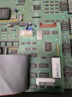
I checked the KB pcb and its dated 1988.

I found a lifted pin on one of the ABI's and thought that was the issue but it must have been a redundant pin as after resoldering it I still got the same issue.

Very occasionally I get a bad ext. PSU error but that happens once in a blue moon and the main toroidal PSU has been reflowed, unless it's trying to tell me the 5v reg. (78M05C) on the KB PCB is a bit flaky which is causing the errors?.

I reflowed all the ABI SM chips now and after putting back the KB PCB it has a flurry of passing self tests without putting pressure on the PCB then fails again with the Z36/6 and 7 error then has another flurry of passing self tests again, so frustrating with an intermittent fault no wonder it took you 6 weeks to fully fix yours
smiley22.gif


Funhouse712022-07-13 22:58:59
 

andrew96

Unfixable? What's that word mean?
Feedback
1 (100%)
Credits
899CR
Funhouse71 said:
I checked the KB pcb and its dated 1988.
Very occasionally I get a bad ext. PSU error

The bad pcb I had was 1991, so not that then

I see the bad ext psu error and on mine it was because I had removed the little ground link wire from the front of the board to the 4mm black socket to be able to remove the board. Once soldered back that error was no more!

I was able compare 2 units and it was still hassle!
 

Funhouse71

Active member
vacBacker
Feedback
6 (100%)
Credits
1,003CR
Every so often when my ABI Boardmaster is cold the machine would have the occasional boot problem, freezing etc. but when the machine had warmed up then it would boot normally, I know other people have experienced the same issue so I thought I would share my fix below.

Anyway the other day it completely refused to boot with either 'BREAK' errors, flashing blocks or orange horizonal lines. Reading up on previous repair logs in this section of the forum a possible cause was the DEC402 prom so I burned a Gal16V8D and booted the machine but still the same issue.

I measured the voltage test points on the mainboard and the only suspicious voltage was the 5V line which was showing as 4.45v...hmmm.

I have recently serviced the power supply with all Panasonic branded 105°C caps so wondered why I would have voltage issues. I saw there was a pot on the power supply marked up as VR1, not knowing what it was for I tweaked the pot ever so slightly and re-measured the 5V line and now I was getting 4.7v :)

When the ABI boots for some reason the voltage is higher then when self test prompt should appear then the voltage seems to drop dramatically down so even though 4.7v was good enough to start the boot process it then would drop lower to the 4.45v and the machine would crash.

I tried in vain to achieve a compromise of not too higher voltage on boot so not to destroy any 5v chips but have enough voltage near as possible to 5V to keep the machine stable but with the existing pot this was proving very difficult!

The voltage seemed to fluctuate wildly during boot anything from 4.45-4.9v prior to 'Self Test' appearing so I suspected the pot itself was a bit flaky.

The pot is a 2Kohm pot and one of the open types with the resistive track open to the elements so I am wondering if this is the reason it's not holding a stable voltage?.

Old ABI Pot.jpg
I didn't have a 2k pot to hand but after measuring the existing one to achieve 5v you need roughly 600ohms so I found a 1K pot and installed that into the power supply.

New Pot ABI.jpg

I set the pot at 600ohms initially then tweaked it higher to get 5v at the main board.

After swapping out the pot my machine has been booting flawlessly ever since with a nice stable 5v.
 
Last edited:

dorkshoei

Newbie
Credits
115CR
I'd been looking for a Boardmaster with the built in display for a while.

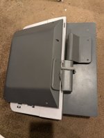
I found one but unfortunately the seller's packing was poor, they didn't secure the screen so during transit the hinge broke and the repeated motion of the panel damaged the actual LCD. Annoying as I really didn't want another repair project.

It is serial BM400231R (no idea what the trailing R means) from 24/5/1991. If you're eagle eyed you'll notice the case for the screen is different, the bezel around the LCD is narrower. It is the same as the one that appeared recently on eevblog. It lacks the backlight.

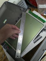
I included a sketch of the dimensions of the case (not to scale). I notice there appears to be an alternate set of 4 unused mounting holes slightly offset from the ones used for the Hitachi panel. No idea what they are for. I've never seen dimensions or pics of the case internals for the earlier backlit screen.

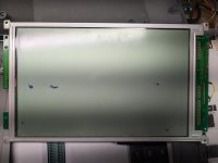
The non-backlit panel is a 11" Hitachi LMG6111XTFR. Not a lot of into on it online. I just posted on vcfed asking for info as it appears it may have been used on early x86/AT portables. One previous person asking here

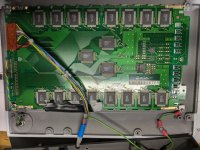
I'm fairly sure the LCD control board is the same as used on the earlier backlit LCD panels. I assume ABI switched as the previous panels were no longer available? It's amusing that the rendering is not quite correctly centered on this new panel, there is a slightly wider gap on the bottom/right (the eevblog one was the same). Best of British quality engineering :)

If anyone has a spare hinge for sale (the half that mounts to the actual screen) please PM me. Otherwise when I get a chance I'll model it in Fusion 360 and make a reproduction.
 

Attachments

  • damage.jpg
    damage.jpg
    75.8 KB · Views: 19
  • LCD back.jpg
    LCD back.jpg
    200.7 KB · Views: 16
  • LCD case internal.jpg
    LCD case internal.jpg
    111.8 KB · Views: 15
  • LCD damage.jpg
    LCD damage.jpg
    94.2 KB · Views: 14
  • LCD front.jpg
    LCD front.jpg
    76.2 KB · Views: 13
  • LCD pcb.jpg
    LCD pcb.jpg
    113.7 KB · Views: 12
  • screen.jpg
    screen.jpg
    64.7 KB · Views: 13
  • screen2.jpg
    screen2.jpg
    86.7 KB · Views: 18
Last edited:

Funhouse71

Active member
vacBacker
Feedback
6 (100%)
Credits
1,003CR
My Screen bracket was damaged pretty much the same way as yours I fashioned up an aluminium plate to secure the 2 halves together, when I get a chance I'll dig the machine out and take a pic of my repair.
 

dorkshoei

Newbie
Credits
115CR
My Screen bracket was damaged pretty much the same way as yours I fashioned up an aluminium plate to secure the 2 halves together, when I get a chance I'll dig the machine out and take a pic of my repair.

Thanks. I plan to model it in Fusion and CNC mill a new one but that won't be happening right away. I need to do something short-term as the screen flopping around makes it even harder than normal to work on the damn thing. I need to make up some extension cords as the wood block propping it open approach doesn't appeal.

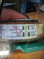
If you're trying to switch one of these to 120v, the following may be helpful. Thankfully the primary PSU is auto-switching.

Attached is a picture of my previous unit (serial 0015)'s UUT psu. You can see the windings are connected to the pcb brown, grey, violet, blue (front to back). For the USA/120v that needed to be jumpered 1->2 + 3->4 (vs 2->3 for the UK).

My latest unit (0231) has the exact same 1st gen UUT psu (not pictured) but the factory decided to connect the wires to the pcb blue, violet, grey, brown (front to back) which is backwards to 0015. That ends up being exactly the same if it's jumpered 2->3 but totally wrong for 120v (1->2 + 3->4 now directly shorts the windings). This orientation needs to be jumpered 1->3 + 2->4.

I also noticed that the two 2-pin connectors plugged onto the new unit's UUT psu were incorrectly oriented (backwards). What I find odd is that it was passing the external psu sense self-test when running like this on USA 240v (jumpered 2->3). The external psu test failed when I was trying to run it on 120v.

Between the two 2-pin connectors being swapped (for reference the 2-pin connector marked with a blue arrow closest to the fuse is the voltage output red/black wires) and the above jumpering issues I was glad that I didn't seem to blow anything on the main boards sense circuitry :)
 

Attachments

  • PXL_20241204_202456343.jpg
    PXL_20241204_202456343.jpg
    68.5 KB · Views: 10
  • PXL_20241204_220235240.jpg
    PXL_20241204_220235240.jpg
    116 KB · Views: 11
  • PXL_20241204_220602966.jpg
    PXL_20241204_220602966.jpg
    90.6 KB · Views: 10
Last edited:

dorkshoei

Newbie
Credits
115CR
what I did was load that file, put the timekeeper ram in, boot it up, set the parameters you want things set to (but not the clock so its stalled at 00 for date and time) get into the security with the 000000 password, clear it with the keyboard space and set it to 'programmer' then remove the timekeeper, read it and store the file, then your have it forever more without having to ever go through that procedure again which I found handy when I was repairing the non working unit as it got corrupted often!. you can use a DS1220Y with no timekeeper and the date and time just remains at 00 00 00 etc

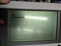
One of my previous units (DEC-402) will only run v2.21 that it came with. Anything newer just results in this screenful of garbage.

This latest unit I just got (with the damaged LCD screen) is running v2.80.

Both have the timekeeper soldered in.

I'm going to try v3.10 on this latest unit but is there is some timekeeper magic I need to be doing?

I just found an email from a guy in Germany I'd been talking to years ago (I don't think he's on this forum) who said "[48T02] there is a memory cell which contains the ROM revision of the BM4K. If you exchange the ROMs, you have to write the new 'revision value' into it"

If I need to desolder and socket the timekeeper and update it with this 'default.tkr' then it might explain why I couldn't get the previous unit to work with v3.10 though the garbage I was seeing on screen doesn't sound like the "lockout" mode I'd read about.
 
Top