Troubleshooting MTC900E

Big Phil

Captain Phil
vacBacker
Feedback
12 (100%)
Credits
538CR
Hi all,

I've been troubleshooting this chasis on and off for a few weeks now.

Firstly, a big thank you to RGP(James) for the facetime and his patience!

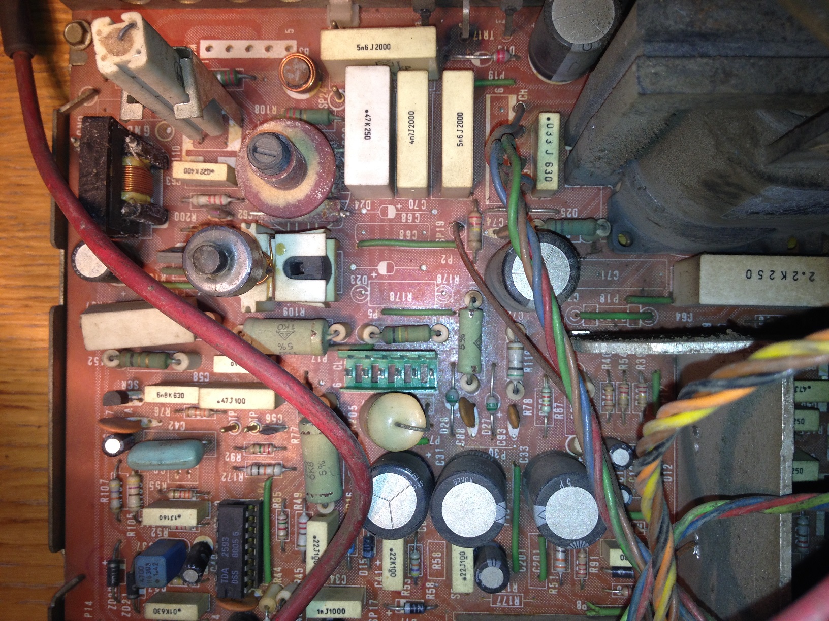
I've noticed that there seems to be some parts missing from the deflection board. See image attached: -

IMG_1624.JPG


Is this correct?
 

astaroth

User
Feedback
2 (100%)
Credits
100CR
I have been troubleshooting the same board over the last month. I finally have it producing a neck glow but am waiting on a new tube.

What's your problem?
 

Big Phil

Captain Phil
vacBacker
Feedback
12 (100%)
Credits
538CR
I don't get any neck glow.

Looking at the bottom of the board, the holes look professionally covered with a bit of flat soldering.
 

PaulSwan

ZZZ
Feedback
1 (100%)
Credits
1,118CR
It's likely intentional. Though this chart is for a 900, the components line up somewhat on a 900E as tube variations...
SAM_4647w.JPG

As others have said, you'll need a meter and a manual :)
Paul.
 

RGP

Meeter & Greeter
Feedback
5 (100%)
Credits
2,039CR
Thats quite common on the 900/E's. There are several revisions of the deflection and power boards - all produce the same result ultimately but some are populated different than others. I must have 4 different revisions across my lot.

Here's where Phil was at when we spoke last week.

Fault - monitor does not power up. Dead from arrival.

ISO is giving the expected 138v to pin 1,2 on the inout connector
B+ is connected to SP15,SP16 and is low at about 115vDC without apparent load - if thr hot/fbt isn't running i expect about 160-175 here normally.
TH2 has had an impedence check and does give readings, it can go bad and gunblade once had to re-wind this to get one of mine going.

I tried to explain isolating the B+ and checking the power section, without 115-120vDC with load you won't get much further.

Desolder the far (deflection end) of sp15 & 16 and attach to 40/60W lightbulb and put meter on volts dc across the lightbulb pins, adjyst RV12 and try and get 115vDC, if you can't get that the issue is in the psu section.

if you can then psu is fine and issue is in deflection area.

Both ordy and gb once said on j+ that 900/E flybacks don't go bad as often as 9000's so it might not be the flyback. Test the HOT at least before diving in anywhere else. You won't get neck glow either until the flyback is getting pulsed by the HOT.

 

abby741

Newbie
Credits
3CR
I tried to explain isolating the B+ and checking the power section, without 115-120vDC with load you won't get much further.
 

astaroth

User
Feedback
2 (100%)
Credits
100CR
I'm pretty sure my problem was the capacitor at the top of your top picture. I changed a fair few things so it may not have been, however that capacitor looked ok on the outside but was mangled underneath once i took it off.
 

Big Phil

Captain Phil
vacBacker
Feedback
12 (100%)
Credits
538CR
Do you see the middle leg of TR17 on the image? It seems to have a dark circle around it. Looks a bit worrying.

What's the best way to test TR17?
 

Purity

The Oracle
vacBacker
Feedback
17 (100%)
Credits
2,999CR
You'll have to desolder it, and test it.

It read as BCE according to this:

http://pdf1.alldatasheet.com/datasheet-pdf/view/22037/STMICROELECTRONICS/BU208A.html

So get your multimeter on diode, and test the following legs:

B + C -
C+ B -
B+ E-
E+ B-
E+ C-
C+ E-
Purity2014-01-21 18:16:00
 
Top