Vector XY monitor kit

myPinballs

Active member
Feedback
16 (100%)
Credits
675CR
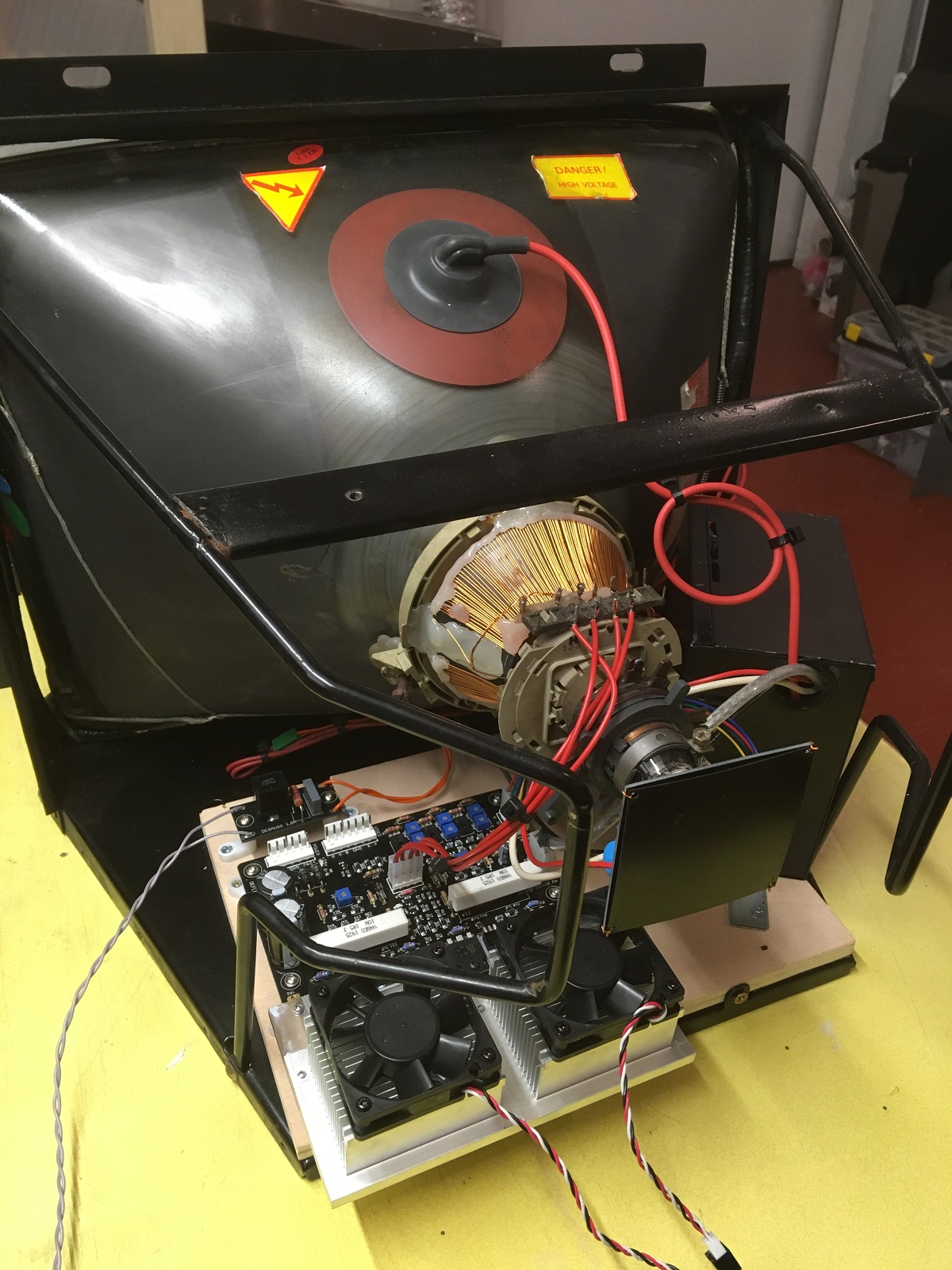
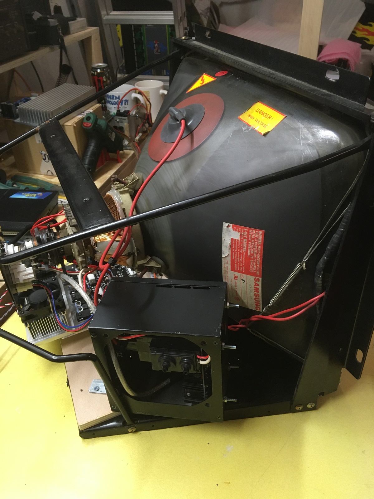
So here is my scratch 14" colour vector build after sorting out the yoke windings. Took awhile but i finally got ~1 ohm in parallel after a few attempts. I used 0.35mm wire and about 100 turns each. Picked up a barry 1.5 deflection & hv kit unused so installed that to. Designed my own neck board for a thin neck as the barry kit neck board was for a fat one!

Just got to fix an x out issue on my orig tempest board that i picked up earlier this year then i can test it all. Hopefully no smoke!!

vector_monitor_scratch_build_with_neck_board_-_1.jpeg


vector_monitor_scratch_build_new_parts_-_2.jpeg
vector_monitor_scratch_build_new_parts_-_6.jpeg


vector_monitor_scratch_build_new_parts_-_9.jpeg


myPinballs2022-05-31 16:30:05
 

Monstermug

Active member
Feedback
23 (100%)
Credits
1,804CR
maybe tidy up the high voltage cables to avoid interferance? also dont forget the fuse inline on the power . u can potentially melt the trace off the deflection board if something goes wrong.
 

myPinballs

Active member
Feedback
16 (100%)
Credits
675CR
Monstermug said:
maybe tidy up the high voltage cables to avoid interferance? also dont forget the fuse inline on the power . u can potentially melt the trace off the deflection board if something goes wrong.

Thanks, i will look at adding the fuses. Interesting that the original atari power brick that i based my remake board on doesn't have fuses for the 25 vac outputs. So should probably add some on to that.
 

Monstermug

Active member
Feedback
23 (100%)
Credits
1,804CR
Yes i learnt the hard way. I used slow blow in line. Forgot how many amps though. Did u turn it on yet? Dont forget that high voltage cap on the crt neck too otherwise u get a shaky image iirc.
 

myPinballs

Active member
Feedback
16 (100%)
Credits
675CR
Monstermug said:
Yes i learnt the hard way. I used slow blow in line. Forgot how many amps though. Did u turn it on yet? Dont forget that high voltage cap on the crt neck too otherwise u get a shaky image iirc.

Not turned on yet, as i'm waiting for the cap neck part and also an op amp to fix the x out on my tempest pcb. Mail is slow this week because of all the holidays.
 

myPinballs

Active member
Feedback
16 (100%)
Credits
675CR
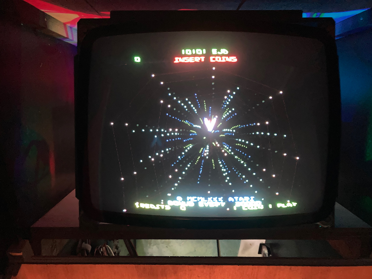
Powered on and no smoke :) Had to spend a few days adjusting and also fixing some tempest board problems. This is what i have now. Still needs some adjustment, but pretty happy so far.
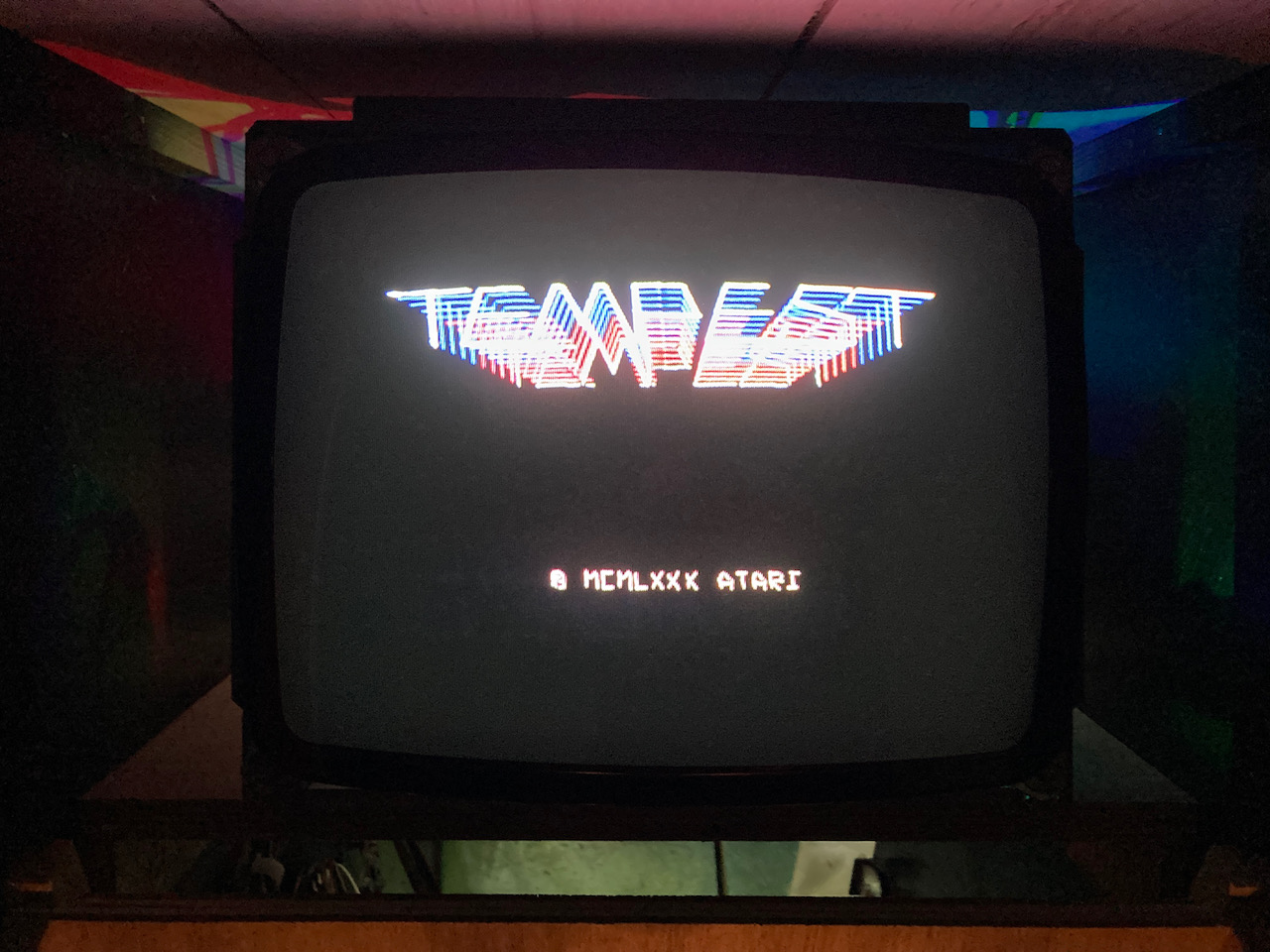
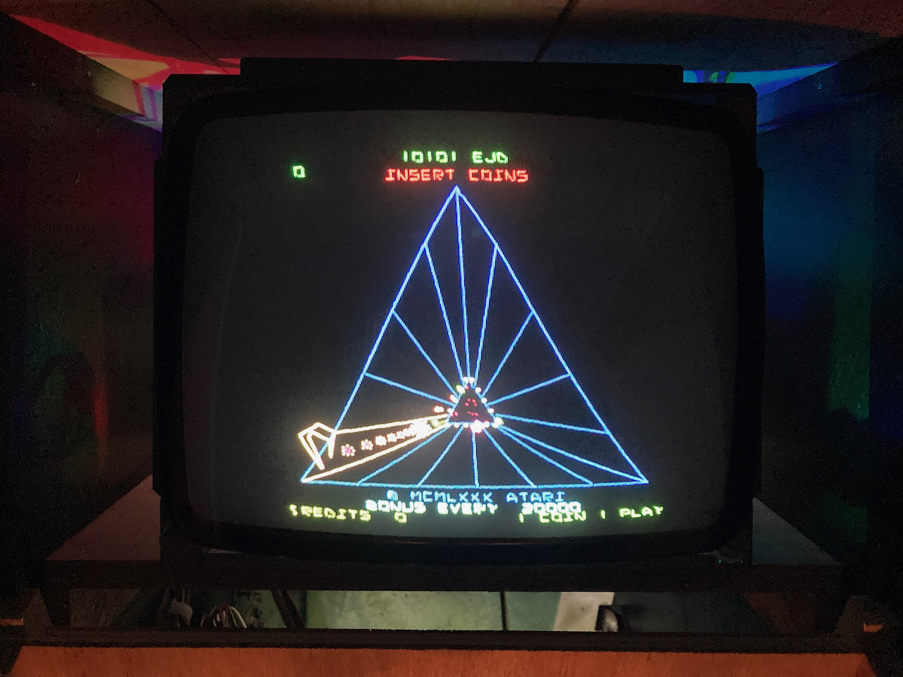
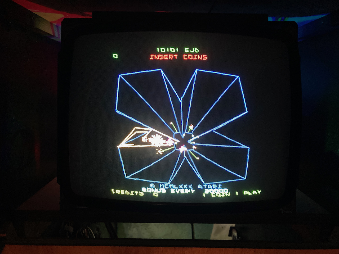
A few things still to investigate/think about:

1) Is there a way to adjust the kind of 'parallelogram ness' of a vector monitor as it seems like when squares are drawn the vertical lines aren’t straight but the horizontal ones are?

2) I see some minor wobble on screen. Anyone know what’s likely cause of this?

vector_monitor_first_run_-_1.jpeg
vector_monitor_first_run_-_4.jpeg
vector_monitor_first_run_-_8.jpeg
vector_monitor_first_run_-_9.jpeg
 

lix

Active member
vacBacker
Feedback
1 (100%)
Credits
545CR
The pincushion correction circuit on Tempest was needed for the WG6100 tubes, either it's not working fully on your PCB or it needs ramping up a bit to cope with your tube and yoke. I don't think there's a manual adjustment for it so it'll require changing resistor values around the MC1495L chips in the correction circuit. That's just a guess though.

I have the same XY kit and get a reasonable picture on my original Star Wars board which has no pincushion correction but I didn't get the coil impedance matching right between the two coils so I'm getting a bit of a convergence issue from top to bottom of the screen. I basically need to redo my yoke winding as I messed up and cut the wire too short after not bunching it up properly.

For the wobble issue, I found that it was magnetic interference from the flyback transformer affecting the yoke, so I had to shield it by putting it in a metal cage. I ended up using the case from a dead PC power supply which does a great job, it's not 100% cured as I've mounted it all in a Hantarex 19" frame so there isn't much room to space the flyback far away from the yoke but it'll do.

IMG_4877sm.jpg


IMG_4880sm.jpg
 

myPinballs

Active member
Feedback
16 (100%)
Credits
675CR
lix said:
The pincushion correction circuit on Tempest was needed for the WG6100 tubes, either it's not working fully on your PCB or it needs ramping up a bit to cope with your tube and yoke. I don't think there's a manual adjustment for it so it'll require changing resistor values around the MC1495L chips in the correction circuit. That's just a guess though.

I have the same XY kit and get a reasonable picture on my original Star Wars board which has no pincushion correction but I didn't get the coil impedance matching right between the two coils so I'm getting a bit of a convergence issue from top to bottom of the screen. I basically need to redo my yoke winding as I messed up and cut the wire too short after not bunching it up properly.

For the wobble issue, I found that it was magnetic interference from the flyback transformer affecting the yoke, so I had to shield it by putting it in a metal cage. I ended up using the case from a dead PC power supply which does a great job, it's not 100% cured as I've mounted it all in a Hantarex 19" frame so there isn't much room to space the flyback far away from the yoke but it'll do.

Thanks so much for the reply, great info and makes total sense on both things. I was wondering if the flyback should be caged and the leads routed more carefully!

I will try the things you suggest :)

myPinballs2022-06-08 16:03:11
 
Top