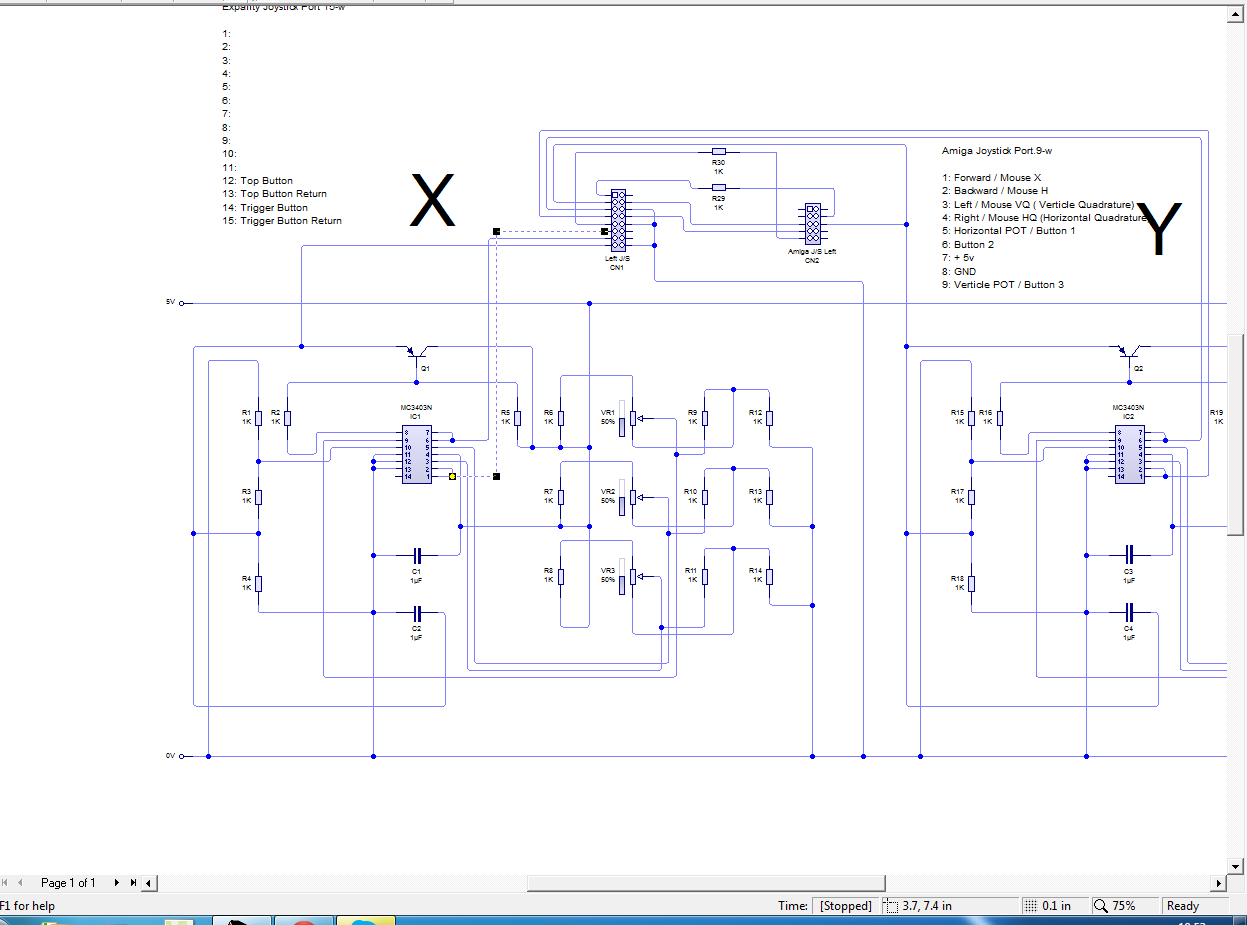
I`m working on trying to figure out the controls on my VR test / Sit Down system.
The `Expality` Computer consists of an Amiga 3000 & a PCB called the FORMAT board. Everything external to the Expality, that plugs into Amiga, goes into the Format Board first.
On the Joystick input, the Format board has a 15pin-D for each left and right J/S. These are both X & Y analogue with 2 independent buttons. The Amiga is connected to this part of the system via the 9pin-D, for the mouse and J/S.
Some of the connections from the 15pin-D go to a `trimming` section on Format pcb. Here there is a grid of preset-pots, L & R Joystick, X & Y axis, in three lines - MIN, CT, MAX.
I have traced the Format PCB the best I can, and I have found that the 15pin connection from the Joystick there are 2 direct ( via a resistor) connections to the 9pin Amiga port. Pins 5 & 9 – Horz & Vert pot input to the Amiga, from pins 1 & 5 on the Expality Joystick.
I assume that as these are direct connections from the Joystick to the Amiga H&V pot connections, that these are the `wipers` at the Joystick pots. ?
After that, each axis has three more wires to it ? I cant understand any way of connecting 4 wires to a potentiometer ?
For each axis I have:
Pin A to Horizontal Pot connection on Amiga. Via a resistor.
Pin B to Op-Amp IC, outputting to MIN Preset Pot circuit. ( Pin 6 = both inputs on Op-Amp, output is to MIN pot)
Pin C to Op-Amp IC, outputting to CT Preset Pot circuit. ( Pin 7 = both inputs on Op-Amp, output is to CT pot)
Pin D to the collector of a Transistor.
Base of Tran connects to Op-Amp input 1
Emitter of Tran connects to Base of Tran.
This Op-Amp`s input 2 is from the MAX pot.
The output of this Op-Amp is to ground via a resistor.
I have tried to connect the 4 wires in each way I can think of to the 3 connection Pot, that would be the X Axis.
On the calibration screen, all I can seem to get is from the X-Axis –100 to 0, OR 0 to 100 depending which wires I connect to the Pot. I cant get –100 to 100 on the scale in any way.
Any suggestions ?
I can try to draw up a circuit diagram if that helps ?
Thanks all!
The `Expality` Computer consists of an Amiga 3000 & a PCB called the FORMAT board. Everything external to the Expality, that plugs into Amiga, goes into the Format Board first.
On the Joystick input, the Format board has a 15pin-D for each left and right J/S. These are both X & Y analogue with 2 independent buttons. The Amiga is connected to this part of the system via the 9pin-D, for the mouse and J/S.
Some of the connections from the 15pin-D go to a `trimming` section on Format pcb. Here there is a grid of preset-pots, L & R Joystick, X & Y axis, in three lines - MIN, CT, MAX.
I have traced the Format PCB the best I can, and I have found that the 15pin connection from the Joystick there are 2 direct ( via a resistor) connections to the 9pin Amiga port. Pins 5 & 9 – Horz & Vert pot input to the Amiga, from pins 1 & 5 on the Expality Joystick.
I assume that as these are direct connections from the Joystick to the Amiga H&V pot connections, that these are the `wipers` at the Joystick pots. ?
After that, each axis has three more wires to it ? I cant understand any way of connecting 4 wires to a potentiometer ?
For each axis I have:
Pin A to Horizontal Pot connection on Amiga. Via a resistor.
Pin B to Op-Amp IC, outputting to MIN Preset Pot circuit. ( Pin 6 = both inputs on Op-Amp, output is to MIN pot)
Pin C to Op-Amp IC, outputting to CT Preset Pot circuit. ( Pin 7 = both inputs on Op-Amp, output is to CT pot)
Pin D to the collector of a Transistor.
Base of Tran connects to Op-Amp input 1
Emitter of Tran connects to Base of Tran.
This Op-Amp`s input 2 is from the MAX pot.
The output of this Op-Amp is to ground via a resistor.
I have tried to connect the 4 wires in each way I can think of to the 3 connection Pot, that would be the X Axis.
On the calibration screen, all I can seem to get is from the X-Axis –100 to 0, OR 0 to 100 depending which wires I connect to the Pot. I cant get –100 to 100 on the scale in any way.
Any suggestions ?
I can try to draw up a circuit diagram if that helps ?
Thanks all!