
What logic chip do I need??

guddler

Busting vectors like it's 1982!
vacBacker
Feedback
10 (100%)
Credits
4,058CR
I want to combine two signals. /OE and R/W.

I want to do something when /OE is low and R/W is high (READ).

I don't care if the output that I perform the action on is high or low as I have control over watching it so I can make the shizz happen on either state.

So what chip do I need (preferably a single one).

guddler2013-10-26 11:21:57
 

guddler

Busting vectors like it's 1982!
vacBacker
Feedback
10 (100%)
Credits
4,058CR
actually, a quick scout on wikipedia shows i probably need to invert one of the signal (7404) and then use a NAND gate (7400) or an AND gate (7408). (or i guess i could use a GAL) Time to go up the shed i guess.
 

trm

Who loves you, and who do you love?
Feedback
2 (100%)
Credits
2,877CR
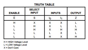
You could do this single chip with a '157

Wire /ENABLE to /OE, Select to R and either pull Input1 high or wire to R. Wire Input0 to GND.

157.jpg


So when /ENABLE (/OE) is low, Select goes high following READ and I1 is gated to Output.

If /OE is high, Output is low. If /OE is low and Select is low, then I0 is gated to Output and I0 is wired low.

trm2013-10-26 11:43:42
 

guddler

Busting vectors like it's 1982!
vacBacker
Feedback
10 (100%)
Credits
4,058CR
I like your style! What I call thinking outside the box there...

I'd have to investigate if I need a pull-up on /OE to prevent phantom outputs but other than that...
 
  • Like
Reactions: trm

guddler

Busting vectors like it's 1982!
vacBacker
Feedback
10 (100%)
Credits
4,058CR
I have a box of GAL22V10B (which I guess would be just as good) sat in front of my keyboard right now but the problem is I've never used them so I'd have to spend the day learning first
smiley36.gif


Other than that I'd have been up for it!
 

guddler

Busting vectors like it's 1982!
vacBacker
Feedback
10 (100%)
Credits
4,058CR
smiley36.gif
At Chappy!

I'm trying to do something with an Arduino - basically implement a crude EPROM emulator and I pretty much think it's simply not fast enough. But before I give up and go to other platforms there's a bunch of things I can try...

The first is to remove all the programming logic from the interrupt service routine (ISR) by implementing it in hardware instead leaving the absolute smallest amount of code for the Arduino to do. That's what I'm looking at here with these logic chips.

Then if that still isn't fast enough (I'm guessing it won't be), I can convert the ISR to assembly code.

Then if that still isn't then I can remove the final little bit of logic by using a buffer chip for output isolation.

Finally if none of that works it's FPGA time. Which will mean re-installing my Xilinx development environment (all 11+GB of it) and a lot of head scratching. Hence I'm keen not to go there.

Oh, and design criteria no.1 - MUST use stuff I already have lying around. It's a ghetto project to lash something together, not project to design the best looking, most sophisticated thing there is
smiley36.gif
 

trm

Who loves you, and who do you love?
Feedback
2 (100%)
Credits
2,877CR
I've got a load of pulled GALs around too and would like to have a twiddle with them especially now Elnec updated my progger software to support writing the fusemaps. But I've not got anything for creating the maps.

So if anybody has links to tools and tutorials I'd be up for that.
 

guddler

Busting vectors like it's 1982!
vacBacker
Feedback
10 (100%)
Credits
4,058CR
I just rigged the logic analyser up to the ROM enable logic and can now see that I have 300ns to read the address bus (two commands) and stick the data on the data bus (one command). But I have absolutely NO idea whatsoever how to know how long my ISR is taking !!
 

trm

Who loves you, and who do you love?
Feedback
2 (100%)
Credits
2,877CR
Is your ISR the two instruction read and the one instruction write?

If so, what CPU is in your Arduino? Should be possible to calculate the cycle counts and from the clock frequency the execution timing. What size data are you reading/writing too?
 

Zabanitu

User
Credits
330CR
eprom emulation should be implemented using a RAM chip loaded with the desired EPROM content.

you can use your arduino to interface the PC with the RAM, taking the file form the pc and loading it into the RAM. Then there will be a socket connected to the ram chip that will go in the real EPROM socket.

here you can find a eprom emulator based on a PIC16F877 and the principle of work

http://www.piclist.com/images/boards/epromemumk2/index.htm

i have made the pcb myself but never had the time to finish it.

in the mean time i've bought a DIGELEC804 programmer (for the infamous 2708) that incidentally is also a EPROM emulator

http://siliconpr0n.org/archive/lib/exe/detail.php?id=prog%3Astart&media=prog:anon:digelec-804:front-panel.jpg

good luck !
 

guddler

Busting vectors like it's 1982!
vacBacker
Feedback
10 (100%)
Credits
4,058CR
Yeah, already tried that but all the buffers became a mass of spaghetti very quickly - I'll go FPGA rather than that!

Why are you using 74LS245's and clamping the DIR pin to GND. Wouldn't it make more sense to use 74LS244's ?? Or was it just what you had to hand.
 

Zabanitu

User
Credits
330CR
guddler said:
Yeah, already tried that but all the buffers became a mass of spaghetti very quickly - I'll go FPGA rather than that!

Why are you using 74LS245's and clamping the DIR pin to GND. Wouldn't it make more sense to use 74LS244's ?? Or was it just what you had to hand.

i have to clarify that the project nor the webpage is mine.... i had a look at it because i was courios and thought it would have been a "nice to have" device for hacking arcade games.

but usually ppl can use MAME without having to mess with eproms and eprom emulators.

btw you're right... the 245s could have been replaced with 244s...

you have a quick eye !
 
Top