yoke flip switch circuit

Retroman839

Senior Member
vacBacker
Feedback
12 (100%)
Credits
7,136CR
just successfully
wired /testing my first yoke flip circuit
tested with a battery and it’s reversing
flipping the + & -

silly question help appreciated
what gauge wire recommended for yoke wire?
don’t want to kill my chassis
smiley18.gif
using to thin a wire
C7FFAF8E-4197-4238-B335-46A73BB82AF1.jpeg


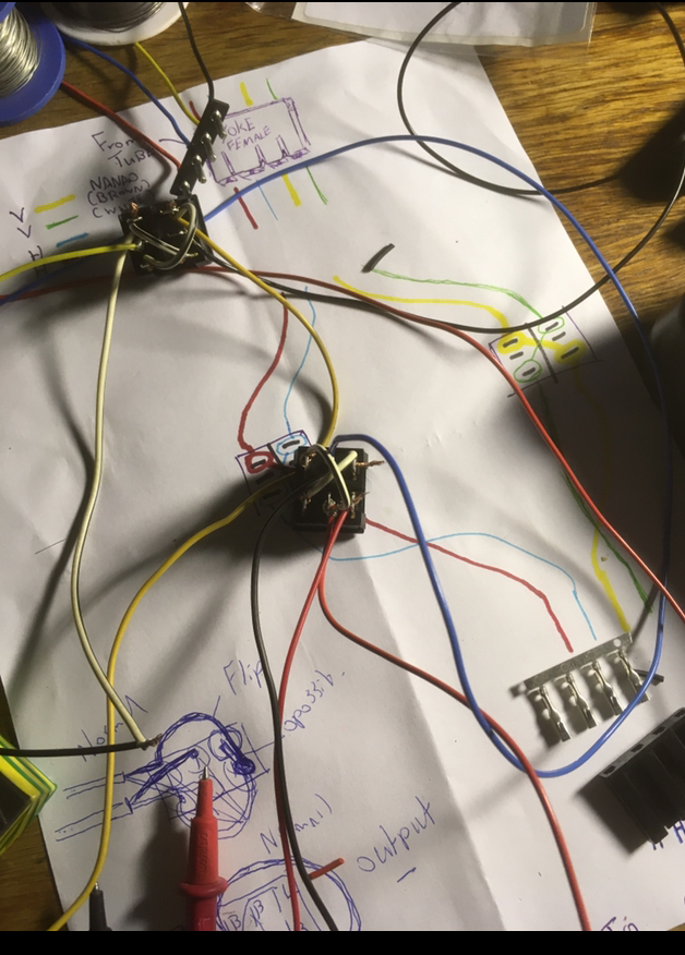
Horizontal wires are noticeably thicker
than the vert i’m wondering what is the
volts /amps going through the wires
here and what would be a good gauge for the vert and for the
hori wires?Retroman8392021-06-20 22:53:17
 

tb2000

Active member
Feedback
4 (100%)
Credits
3,084CR
Horizontal voltage is quite a bit higher than vertical, that's probably why the wires are different gauges. Also, it's best to flip the switch when the chassis is off to avoid damaging the deflection circuits (although you can do it whilst switched on, best not to take the chance really). Whilst the wires are usually all the same thickness on a 20" and smaller crt, the horizontal is usually a bit thicker on 25" and larger crts as the deflection voltage is a bit higher (as far as I can remember anyway).
 

big10p

Coins detected in pocket!
vacBacker
Feedback
12 (100%)
Credits
5,581CR
tb2000 said:
Horizontal voltage is quite a bit higher than vertical, that's probably why the wires are different gauges. Also, it's best to flip the switch when the chassis is off to avoid damaging the deflection circuits (although you can do it whilst switched on, best not to take the chance really). Whilst the wires are usually all the same thickness on a 20" and smaller crt, the horizontal is usually a bit thicker on 25" and larger crts as the deflection voltage is a bit higher (as far as I can remember anyway).

Out of interest, what sort of voltages are going through the yoke wires?
 
Top