[back!] Tempest - Plays blind but tube has glow

Jodo

Boy is this a machine!
Staff member
vacBacker
Feedback
15 (100%)
Credits
607CR
OK - before I get into detailed measuring, I've had the screen out and done a visual inspection whilst I wait for posty to drop my PCB off.

Checking component by component, there is nothing (obviously) fried. All 4 fuses on the deflection PCB are good with good connections.

I then checked the edge connector and I found that the key plastic on pin 3 had been pressed over onto pin 4 (-22 VDC) and was preventing a good connection (if any). I am not sure if pin 4 could cause no picture / resetting but it appeared to be blocked.

Would that result in the symptoms described?

Jodo2012-09-19 13:25:45
 

guddler

Busting vectors like it's 1982!
vacBacker
Feedback
10 (100%)
Credits
4,055CR
Quite possibly. +/-22v is usually used in vector pcbs to derive the voyages for the analogue output section. If were a betting man I'd say you've probably found the problem!
 

Equites

Chief Sheesher®
vacBacker
Feedback
35 (100%)
Credits
3,320CR
Jodo said:
OK - before I get into detailed measuring, I've had the screen out and done a visual inspection whilst I wait for posty to drop my PCB off.

Checking component by component, there is nothing (obviously) fried. All 4 fuses on the deflection PCB are good with good connections.

I then checked the edge connector and I found that the key plastic on pin 3 had been pressed over onto pin 4 (-22 VDC) and was preventing a good connection (if any). I am not sure if pin 4 could cause no picture / resetting but it appeared to be blocked.

Would that result in the symptoms described?

Sounds like the problem, like I said, what do you expect after 30 years? Replace that edge connector, ideally both.
 

Jodo

Boy is this a machine!
Staff member
vacBacker
Feedback
15 (100%)
Credits
607CR
OK. Correcting the key position in the edge connector gave me picture again...but the same fault exists - it ran rock solid for 20 minutes then started resetting faster and faster until the spot killer kicks in and no picture at all.

I let it cool down for 15 mins or so and then she booted up fine. 20 minutes later it was reset city again.

I can't see how the monitor being faulty would cause the game to reset (correct me if I'm wrong), and we know it's not the PCB now; so it's looking like a voltage issue. I'll go over this thread again and start measuring.

The difficulty is I have to wait (I suspect) until it starts resetting before I measure, otherwise it's going to read fine if I measure straight away?

*EDIT* I forgot to add that when it starts resetting, it is accompanied by interference from the speaker which is not present during normal play.

Jodo2012-09-19 17:22:11
 

Jodo

Boy is this a machine!
Staff member
vacBacker
Feedback
15 (100%)
Credits
607CR
A thought - could I drop the power brick from my Star Wars upright into the Tempest? Are they interchangeable without any modification? That would discount / prove if this was a power brick issue
 

karlcdoe

Active member
vacBacker
Feedback
8 (100%)
Credits
881CR
Well, it's unlikely to be the monitor bearing in mind the problems you currently describe, you could run the game with the sound up and the monitor disconnected (which also removes power to monitor) and see if it still resets to rule it out.

If the board really is 100% get a multimeter and some croc clips and leave it attached measuring the +5v on the game PCB test points -this should also highlight any stupid voltages coming from a dodgy edge connector. You need to confirm if the 5v line is
dodgy at the pcb (or dummy load), then see if it is also dodgy at the
AR2 output measuring on the AR2 itself and if so then check the input to
the AR2. crap in == crap out so if the input is sh*te then it's the brick, or that part of the
loom.

I am not sure that any of the other voltages from the AR2 would cause it to crash and reset but I'd start with the +5, maybe someone else can confirm?
 

Jodo

Boy is this a machine!
Staff member
vacBacker
Feedback
15 (100%)
Credits
607CR
karlcdoe said:
If the board really is 100% get a multimeter and some croc clips and leave it attached measuring the +5v on the game PCB test points -this should also highlight any stupid voltages coming from a dodgy edge connector. You need to confirm if the 5v line is
dodgy at the pcb (or dummy load), then see if it is also dodgy at the
AR2 output measuring on the AR2 itself and if so then check the input to
the AR2. crap in == crap out so if the input is sh*te then it's the brick, or that part of the
loom.

I am not sure that any of the other voltages from the AR2 would cause it to crash and reset but I'd start with the +5, maybe someone else can confirm?

I have it on and testing +5v now as you describe. It's reading 5.11 VDC though - a little high or OK?

Monitor is unplugged.

Theoretically after 20 mins we should see some change...
 

karlcdoe

Active member
vacBacker
Feedback
8 (100%)
Credits
881CR
so.. according to the Star Wars schematic package I already have open in front of me.

You should have 10.3 VDC (unregulated) coming into the AR2 between pins 3/5/6 (+ve) and 1/2/4 on connector J6 (don't be surprised if it reads a tad higher than this)

The output of +5v should be on J7 between 5/6 and 1/4 on connector J7. I am not in front of a machine to confirm but I'm pretty sure there are test point on the AR2 for input and output anyway.
 

karlcdoe

Active member
vacBacker
Feedback
8 (100%)
Credits
881CR
I don't think 5.11v will kill anything immediately (if at all), I'd adjust it down a fraction lower later as it might just complicate things at this point... If you see something like 7v on the meter even briefly I'd hit the off switch as that probably is a sense line fault or general psu issue.
 

Jodo

Boy is this a machine!
Staff member
vacBacker
Feedback
15 (100%)
Credits
607CR
Had to kill that test as the +5v reading from the game PCB started going up - it went to 5.29v so I switched it off and swapped out the AR II.

Testing started again - game board +5 voltages reading 5.02v.

Waiting to see if it starts going up again after 20 mins or so.

*EDIT* Are there any voltages I can measure at the block that goes into the back of the WG6100 to see what it's getting; what pin numbers should I probe and which is GND etc...any advice?

Jodo2012-09-19 19:47:33
 

Jodo

Boy is this a machine!
Staff member
vacBacker
Feedback
15 (100%)
Credits
607CR
Well the board seems rock solid under another AR II; no resets and no voltage ripples.

The problem now is when I reconnect the monitor I get nothing but vague out of focus clouds of moving colours and I have to kill the power because after 30 seconds of that something starts to smell.

As there is only 1 block that plugs into the back of the WG6100 - it must be fairly easy to ascertain if it's getting the correct voltages?
 

Jodo

Boy is this a machine!
Staff member
vacBacker
Feedback
15 (100%)
Credits
607CR
Just ordered the following; it won't hurt to get the WG rebuilt:

LV2000 v2 - Low Voltage Power Supply Retrofit for WG 6100 Color XY Monitors

Wells Gardner 19" 6100 Color XY Monitor Rebuild (cap/transistor) Kit

Wells Gardner 19" 6100 Color XY Extra Parts Kit
 

karlcdoe

Active member
vacBacker
Feedback
8 (100%)
Credits
881CR
The PSU for the monitor is a center tapped transformer winding of 50v AC. It comes straight from the power brick, it should be pins 13, 14 and 15 on the connector that goes into the back of the monitor.

So to recap is the board now playing blind with no resets? It is possible to damage the monitor if the game board is giving out spurious signals, it might also make is smell hot. It's difficult to tell from the description if the board is outputting garbage or the monitor is playing up. It could be showing out of focus objects because of a monitor fault on the HV, or it could be that the game pcb is trying to draw vectors way outside the visible screen range. Either way I wouldn't leave it runnning like that for any length of time. Is there anyone near you with a scope that can hook it up to the game pcbs as installed in the cab to rule everything out except the monitor? Something screwy is going or you have more than one intermittent fault.
 

karlcdoe

Active member
vacBacker
Feedback
8 (100%)
Credits
881CR
Incidentally the wiring diagram for the upright cab can be found here:

http://arcarc.xmission.com/PDF_Arcade_Atari_Kee/Tempest/Tempest_DP-190-2nd-01B.pdf

As regards the AR2 voltage floating, it should stay pretty stable based on the readings from a star wars PCB during recent testing: I adjusted it to fractionally over +5v at the pcb and it stayed there through several hours of (miserable, gruelling) pcb fault finding. Apart from cleaning the connectors all I had done on that AR2 was slowly rotate the +5v pot a few times throughout its range to clean the pot and replace the 2N3055 transistor.
 

Jodo

Boy is this a machine!
Staff member
vacBacker
Feedback
15 (100%)
Credits
607CR
Hi,

The game now plays blind with no resets and passes test mode as far as I can tell.

The spot killer doesn't come on at all now. It's just the coloured patches that change in time with the game but as you say I can't leave it on because of the smell / damage risk.

When you say pins 13, 14 and 15, to be completely clear I need to know which pin I'm placing the black probe in and which the red..(sorry for my noob ness..)
 

karlcdoe

Active member
vacBacker
Feedback
8 (100%)
Credits
881CR
set the meter to AC volts on a suitable range. put the black lead on pin 14 of the monitor connector and the red on pin 13 and then move the red to pin 15. You should see around 25-30 volts in each case.
 

Jodo

Boy is this a machine!
Staff member
vacBacker
Feedback
15 (100%)
Credits
607CR
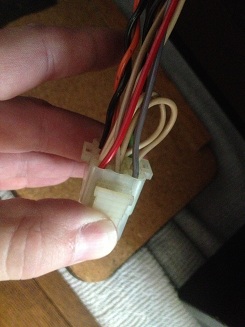
OK - I'm getting no readings of any kind when set to 200 range AC, so it's picture time I'm afraid - which colours exactly should I be probing please:

voltage_001.JPG
voltage_003.JPG
 

karlcdoe

Active member
vacBacker
Feedback
8 (100%)
Credits
881CR
hmm, bit difficult to see the colour in the pix but I think it's the three wires nearest the camera lens in the second photo. The schematics in that link I posted are colour coded BN, GY and BN which sounds like brown / grey / brown to me.

Sadly I can't simply go and look in back of my Tempest as it had been converted to 1942 when I got it and I wired it up pretty much from scratch using anything that was laying around at the time.
karlcdoe2012-09-20 15:55:50
 
Top