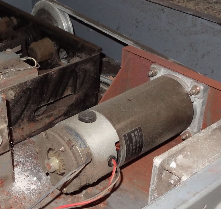
Outrun DLX Sitdown Motor

PhilT

Active member
vacBacker
Credits
154CR
Hi

Been working on getting the seat movement on my Outrun working, naturally the motor controller board was broken initially so when I got the that board working, the next thing to break would be the motor itself, and true to form the old girl has delivered!

Had it tested by a local company that rebuilds electric motors and the report back is that the permanent magnets in the motor are only about 10% of the strength they would expect them to be. That does explain why it works with no load but judders and moves the seat very slowly when fitted.

So the question is am I sc***ed or is there a replacement, equivalent, that can be fitted. Looking round I see no 80V 3500rpm DC motors with a clutch mechanism. The rebuild company does not know of any and they are in the trade so its not looking hopeful.

Otherwise its experimental surgery! re-magnetisation - described by the company as expensive, unpredictable and not an 'exact science' - hmm

Any pointers gratefully received.
 

tin

Active member
vacBacker
Feedback
3 (100%)
Credits
649CR
Interested in what comes out of this too. No suggestions atm though sorry.

<edit>

Just went down the rabbit warren, and it seems there are a lot of places that make 80v motors, seems they are used in fork lifts, rollertrucks etc. Wondering if such a thing would fit and suffice - something like
http://www.directindustry.com/prod/johnson-electric/product-665-1217073.html#product-item_1217075

Next time I get the motor out of mine I'll check out the specs, see if it's actually intended for a fork lift!

tin2017-08-14 21:45:52
 

PhilT

Active member
vacBacker
Credits
154CR
I dug out the basic specs a while back they were:

Techs Corporation Japan (Kanagawa Japan)

DC Magnet Motor

Type DMW-180SB2

395 Watt

80V DC

RPM 3500

Integrated clutch 24V DC

Code:
 

PhilT

Active member
vacBacker
Credits
154CR
The people who tested the motor came back to me and as they cant find any technical specs for it, the re-magnetising or whatever you call it option is not even available so looks like I have a scrap motor.

They made some suggestions but they were all way over voltage, ran slower than 3500rpm (usually 3000) and came with a hefty price tag >£500 new.

Thoroughly pissed off now.
 

ColinD

Active member
Feedback
6 (86%)
Credits
1,367CR
I'd be tempted to chop in a cheap 400W brushless servo motor and controller for about £100 once I'd worked out how the control signals work and made something to interface in between the game board and the controller. Doesn't matter about the motor speed as you set it with the controller.
 

PhilT

Active member
vacBacker
Credits
154CR
no https://www.parvalux.com/ wasn't mentioned.

I spent some time with the schematics for the driver board, and it controls the 80v line directly to the motor and a separate 24v line for the clutch. Thinking i may be able to repurpose a electric scooter motor like this:

http://www.ebay.co.uk/itm/Electric-MotorE-scooter-48-volt-800-watt-11-tooth-Brand-New-/261533823820?hash=item3ce4a1734c:g:CmMAAOSwCmZZR7qP

See if i can change the tap from the transformer to pick up a lower voltage or step it down with a regulator.

Then need to do something with the clutch but not sure when the clutch is actually used. I am hoping it might just be used to lock the seat in the 'home' position when the game is not in play. I think i might be hooking up a light to it to see when its released during play.
 

tin

Active member
vacBacker
Feedback
3 (100%)
Credits
649CR
So Parvalux say that they do custom stuff, so wondered weather worth speaking to them.

Same here for how the board controls the motor, just sending it voltage.

I wondered about the clutch too, if I get mine working I will bang a multimeter on the 24v and see if it reveals when it's used.
 

PhilT

Active member
vacBacker
Credits
154CR
the original motor has a v-belt pulley wheel on it, not a toothed cog to take a chain. will have to change that to get the gearing something like anyway.
Havnt got the motor so cant take a quick pick, its still at the place i took it for testing. but heres a pic of one:

outrunmotorinsitu.jpg
 

PhilT

Active member
vacBacker
Credits
154CR
tin said:
So Parvalux say that they do custom stuff, so wondered weather worth speaking to them.

Problem with the custom stuff is that companies charge megabucks for it and I really cant justify it, although it would be nice...
 

JohnBud

There's only one JB, only one JB!
Feedback
2 (100%)
Credits
429CR
try searching pyongyang mobility or similar. the motor and brake is similar and both run at 3,500 rpm. i could be wrong but i don't think voltage is an issue ??? the bigger motors will run at 100 amps.
 

PhilT

Active member
vacBacker
Credits
154CR
Did some hunting around for those mobility motors and they all ran at 24v. Voltage affects motor speed so pushing 3 times the voltage through them cant be good.

It did lead me to another possibility though - treadmill motors. Most are 220v but some are 100-130v at around 4000rpm. Dropping the voltage to 80v should get us in the right area speed wise and they are all over 1000 watts so more than powerful enough.

No clutch though so thats something that will have to be retro fitted but i wont worry about it for now.
 

tin

Active member
vacBacker
Feedback
3 (100%)
Credits
649CR
I tried to disassemble mine but it wasn't happy about it, however looking at the photo again I really see what you mean! will try again!
 

Fantazia2

Active member
vacBacker
Feedback
13 (100%)
Credits
2,192CR
Just taking another look at it, I'm assuming that the bit at the opposite end to the V-Belt with the wires coming out and the blue? label is the clutch

So what exactly is its purpose as with it being on the opposite end to the drive pulley the only thing I can think of is that the clutch acts as a brake when activated to stop the motor spinning, otherwise if its purpose was to attach and remove the motor drive from the pulley then the motor would have to have a shaft within a shaft, or am I missing something.
 

PhilT

Active member
vacBacker
Credits
154CR
The clutch is on the opposite end to the pulley so its the end bit you can see in the photo above. Theres some friction material and springs and a solenoid that operates the clutch when 24v is applied. Its bolted into mounting on the motor.

I think its acting as brake-on-by-default as all it does is engage and disengage the friction material, it has no effect on the pulley, thats always engaged. You engage the clutch by applying voltage, that release the friction material allowing the motor to spin. Remove the voltage and the clutch disengages, the friction material is then clamped together by the springs so it brakes the motor.

Wish I knew how the not-so-permanent permanent dc motor magnets got demagnetised (wow thats a mouthful!) but I dont know. I took it apart, cleaned 30 years of crap out of it and put it back together again the same day. I have done some reading and I saw something about having to be careful maintaining fields if things are apart for any length of time with certain magnet types but it all looked like black magic to me. I may very well have caused it myself I just dont know.
 

PhilT

Active member
vacBacker
Credits
154CR
re the voltage it uses, as far as i can work out

motor is supplied with 80VAC straight from the transformer

this then continues it merry way into the motor driver board then to ground

the driver board, under direction from the game board, then half rectifies the AC into DC+ and DC- to control the direction the motor spins

there may be some PWM going on to control motor speed but I dont know

the clutch is controlled by a separate 24v line

I have not seen schematics specifically for the Outrun motor board but Space Harrier uses the exact same pcb, the only difference is that Space Harrier controls 2 motors so when you look at the Outrun board some of the board components are not populated as it only controls one.
 
Top