You are using an out of date browser. It may not display this or other websites correctly.
You should upgrade or use an alternative browser.
You should upgrade or use an alternative browser.
Arm Champs 2 power confusion
- Thread starter Davespice
- Start date
I have always said to many learner drivers … to fail your first test you will perhaps often look back and consider it the best driving lesson you had at an early stage! Second time round , less nervous and you know what is expected!
So too is sometimes, realising a mistake, owning up and it makes you that bit more aware in the future before rushing ahead .
Well done ! just remains now to get the necessary repairs done and hope for a good outcome … I think most of us have been there ? That’s why the pin 7 Jamma edge connect keyway is often termed the ‘idiot key’ as when the loom plug has its blank in place it’s impossible to mount a pcb upside down , or off alignment .
I know plenty who have managed that error… not least also missing the label that says Sega or CAPCOM etc and not thinking ?
Last edited:
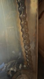
Hi folks, so I've been on holiday for a few weeks and only just returned to working on this machine. I have vacuumed and cleaned the bottom internals now and it's looking a lot better, I can see where everything is now. My next step will be to get mains power from the wall socket into the power board (as seen in the previous post above). The mains switch looks really corroded, see picture, and I'm not sure if I can trust it. Should be easy to test though but I think I need to take the whole thing out to clean it and make sure there's no corrosion that might create a short circuit. I am also wondering if I need to do anything with the drive chain, seems to be covered in a kind of grease - doesn't look completely dried out though.
So any advice on either of these would be welcome, does anyone know what type of switch that is? It might be better to just replace it.
So any advice on either of these would be welcome, does anyone know what type of switch that is? It might be better to just replace it.
Attachments

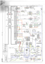
Hi folks, so a lot has happened with this machine since I last posted. We are making reasonable progress with it - right now though I really need to find the electrical schematic for the motor driver board, marked on the schematic with the number AC-92115 (PCB also has the silkscreen mark saying EB91042-20052 MADE IN JAPAN). We are not getting any LED activity or voltage coming out on black/white M-OUT lines of TB-2. It looks like someone had previously tried to remove the MA2440 attached to the big heat sink in the middle because there was some flux residue under there - but it looks like they were unsuccessful in the removal and gave up. So I am suspicious of that chip.
If anyone knows where I can find the schematic I would be very grateful! 🙏
If anyone knows where I can find the schematic I would be very grateful! 🙏
Last edited:
K1ngarth3r
Active member
I notice you have a manual for this game @Davespice would it be feasible for you to make a scan of that?
Hmm, guess you could check that ma2440 out with a meter. Says it takes between 90-132vac and outputs 12vdc at 6.5amp max and can handle a temperature up to 125°C. Can't find a pinout but have seen the component shown with 3 of the 7 legs cut off. Maybe a good pic of the circuit board top and bottom might be useful.
Hi folks, we made some progress with this - it turned out that the VGA converter board (which was installed to accomodate a flat screen monitor to replace the CRT) was broken, so we swapped it out for a different board and now we have video output.
However as you can see we have sprite problems, the background is showing fine (sound is also working) - but you don't see the opponent sprite and the text characters are all messed up. So I plan to give the game board a proper clean as this kind of thing can often just be a bad connection in a corroded socket. Failing that potentially a corrupted ROM image (we've got all the tools needed to deal with that).
The other thing I have done is tracked down a company who may potentially have the electrical schematics for the main game board and the motor driver board in their archives: https://www.city-connection.co.jp/
They apparently acquired the rights to the JALECO assets in 2014, so I wrote them the email below:
件名:『アームチャンプスII』(1992年)アーケード筐体の技術資料(回路図)に関するお願い
株式会社シティコネクション 御中
突然のご連絡、失礼いたします。
私たちは現在、1992年にジャレコより開発・発売されたアーケードゲーム『アームチャンプスII』の修復プロジェクトを進めております。この修復は、欧州宇宙機関(ESA)のレトロコンピューティングクラブ内での個人的な取り組みであり、ヴィンテージハードウェアおよびソフトウェアの保存・研究を目的とした非営利活動の一環です。
本プロジェクトにおいて、メインゲーム基板およびモータードライバ基板の修理が必要となっておりますが、これらの電気回路図や技術資料を入手することができず、困難を感じております。
2014年に貴社がジャレコの資産を継承されたと伺っており、『アームチャンプスII』に関する技術資料がアーカイブとして残されている可能性があるのではないかと考え、ご連絡させていただきました。
もし可能であれば、メインPCBおよびモータードライバ基板に関する回路図やサービスマニュアルなどの技術情報をご提供いただけませんでしょうか。部分的な情報でも結構ですし、資料の所在に関するご助言だけでも大変ありがたく存じます。
この要望はあくまで非商業的かつ保存目的のものであり、クラブ内での研究・修復活動に限定されております。
ご多忙のところ恐れ入りますが、何卒ご検討のほどよろしくお願い申し上げます。ご返信いただけますと幸いです。
敬具
Fingers crossed we get a reply! 🤞
I found a picture of the top on my phone, I can make a picture of the bottom at some stage.Hmm, guess you could check that ma2440 out with a meter. Says it takes between 90-132vac and outputs 12vdc at 6.5amp max and can handle a temperature up to 125°C. Can't find a pinout but have seen the component shown with 3 of the 7 legs cut off. Maybe a good pic of the circuit board top and bottom might be useful.
Attachments

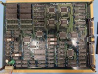
Also uploading some pictures of the game boards. Can anyone help identify the thinner socketed chips on the lower board? I am guessing CH9072 could be the "character" roms? You might have to download the files to zoom in a bit - but some of those chips look like they are not sitting straight inside the sockets. Perhaps that could account for why the text is all messed up (see previous video). But the other problem is that we do not see the large sprites for the opponents, and I am guessing those are the larger 27C eproms on the top board.
Attachments
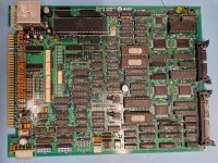
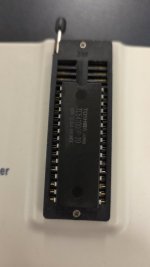
Okay so we had a breakthrough with the graphics. We made a test rig allowing the game board to be run in a flattened configuration outside of the cabinet and had been probing the bottom gfx board with the oscilloscope (where we assumed the problem was). Nothing was looking suspicious so before moving onto the top board we decided to dump all the ROMs for comparison to the MAME set (via MD5 checksum). We used a GQ4x4 for this. Did that for all of the six mask ROMs on the bottom board and they all checked out fine. Then with the top board they all checked out except for one which was IC99 in the top right corner. This chip was actually returning a different binary file each time we read it out, it was also a different type to all the others. It was a Toshiba TC541000P-20 (being used in place of a 27C010). We also tried to read it out using a few different settings on the GQ4x4 but it was a different read out each time (and different with the same settings). So a colleague found an AMD 27C010 in the back of a drawer at work and we burnt a new copy of IC99 using the file from MAME, popped it into the board and bingo; text corruption was gone. For me this is the third time that a file from MAME has been used to save a game. So many people out there think MAME is a gaming project, it's totally a preservation project. What I didn't manage to do was put it back into the cabinet yet to see if the rest of the missing sprites are back, to get the game to start we've been manually moving the arm left and then right to fool it into thinking the motor test was passed. So I'll do that on Monday most probably.
If all is well the next thing to solve is the motor driver board and then potentially the machine will play. I didn't receive any reply from City Connection (the company that owns the rights to Jaleco games) about the electrical schematics. At this point I would assume my email was ignored, bit of a shame but they look like a shell company with the only purpose of setting up licensing to monetize various types of acquired assets.
I think the next thing I will do is try connecting the motor to 80VDC to see if it will still move, I'm wondering if I should take it apart to clean too.
Attachments
Exactly. F is for Fast, T is for Time Lag (slow)With fuses you need to look on it and see if it's a F2 or T2, that determines whether it's quick blow or slow blow but can't for the life of me say which is which.
Also, the fuse looks vaporised, so check the bridge rectifier and other things after the fuse for any dead shorts before powering up.Hi folks
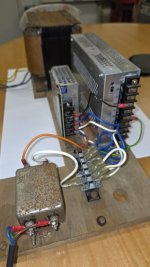
So I'm working on a Jaleco Arm Champs 2 - it is in semi poor condition. Internally there is metalic corrosion on the upward facing surfaces - as if the machine was exposed to some corrosive dust like plaster dust in the past. So for example the top surfaces of the PSU cages are corroded but the sides are all totally fine.
The machine has a UK plug on the mains lead but the internal PSUs look like US mains ones still - I took them apart to check/clean and found they had 125V 2A fuses in both of them. I attach a few pictures of the smaller one. I tried to power it up using 230V mains (before I realised the input voltage) and of course the fuse went bang. Does anyone know if these are slow or fast blow? I have a 1500W step down transformer for US mains to try it with but need to replace the fuse now.
I am looking at the schematic and mains voltage is going to various places from the Faston Terminal at the bottom (C8) - especially it goes to the Motor Control board in the middle (C5/6) which is labelled as 100V (see TB1 pins 1 and 2). So I am thinking that it probably is not good to supply 230V mains power to that board right - as I would imagine that power is being switched to the motors.
I am wondering if the UK plug is just a red herring, does anyone know if these machines can be run on 230V but with the two PSU units replaced? Or would that cause damage to the motors if run on that voltage?
Thanks in advance
Dave
P.S. Any advice on renovating these things would be gladly received.
Oh that PSU was actually found to be sagging under load, and we replaced it with a modern one that is powerful enough to do the job of both of the originals.Also, the fuse looks vaporised, so check the bridge rectifier and other things after the fuse for any dead shorts before powering up.
Last edited:
T2 slowWith fuses you need to look on it and see if it's a F2 or T2, that determines whether it's quick blow or slow blow but can't for the life of me say which is which.
F for fast
Update folks.
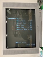
Okay so replacing the EPROM at IC99 has partially fixed the graphics, we see correct text everywhere now. But we are still not seeing the bad guy sprites, and advice here would be appreciated.
As a next step I plan to check the 45 nanosecond EPROMs on the bottom board (the ones marked CHXX). Because these are so fast access it makes me think they are storing things like palette data or sprite tile sequence data - which if corrupted could result in not seeing entire banks of sprites.
The chips in the board are type 27CX642 which are 8K in size, when I remove them there's a text mark on the silkscreen saying 27CX322 (which is 4K) - and interestingly the MAME source comments lists these as Atmel AT27HC642R (which has the same pinout as the 27CX642). The difference between the 322 and 642 types is that the 322 has two chip enable pins. The second chip enable pin is actually A12 (address pin) on the other two. Maybe they put the data in twice, so if A12 is set is still reads the same data out? Anyway I plan to dump these and compare them to the MAME files too.
Also - please no more comments about fuse types - read the whole thread!
Here you go, sorry it took me so long to get around to doing this.I notice you have a manual for this game @Davespice would it be feasible for you to make a scan of that?
Attachments
K1ngarth3r
Active member
Thank you very much.