You are using an out of date browser. It may not display this or other websites correctly.
You should upgrade or use an alternative browser.
You should upgrade or use an alternative browser.
Asteroids Deluxe Cabaret - Scratch Build
- Thread starter myPinballs
- Start date
myPinballs
Active member
Bods said:Power brick which would be similar

Thanks for that. Very useful
myPinballs
Active member
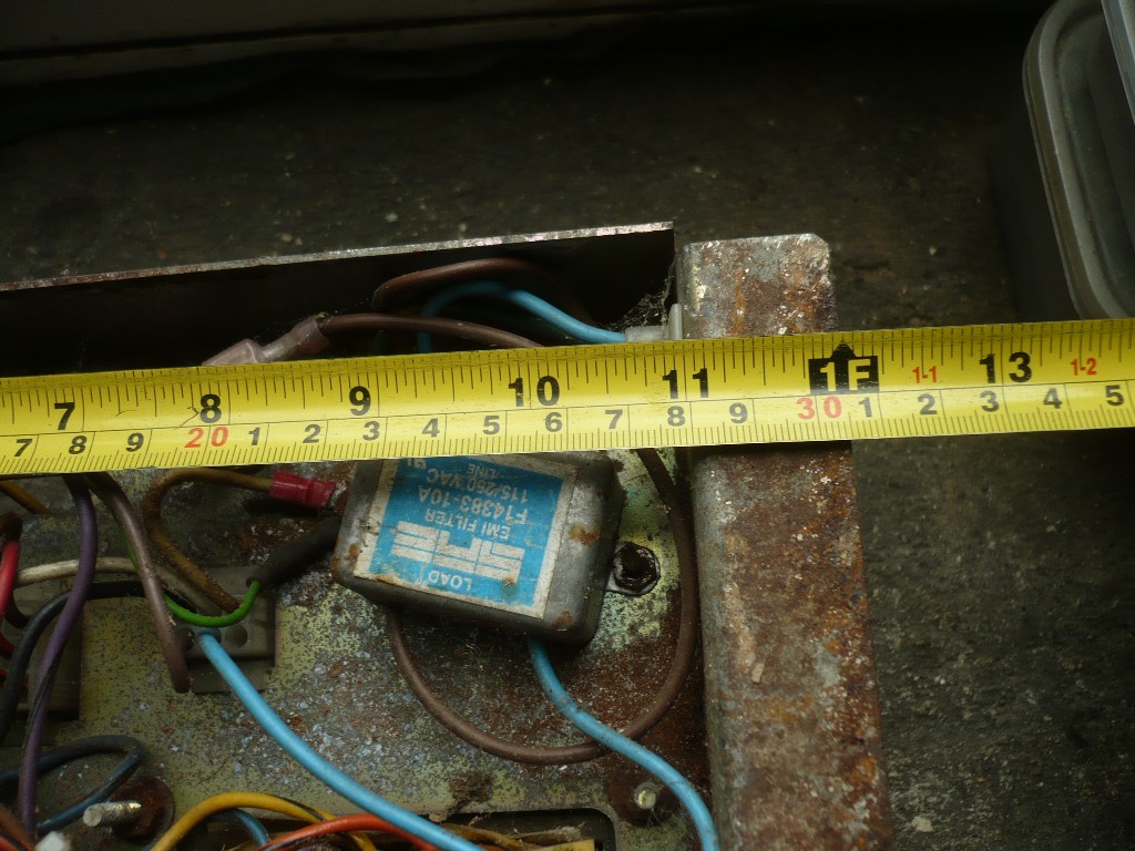
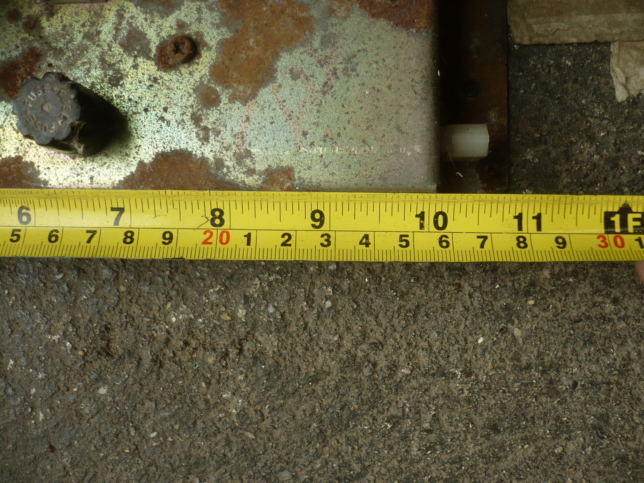
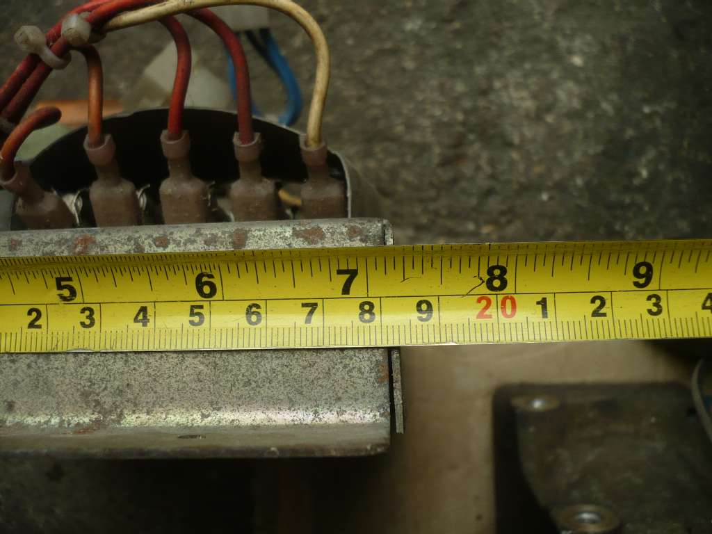
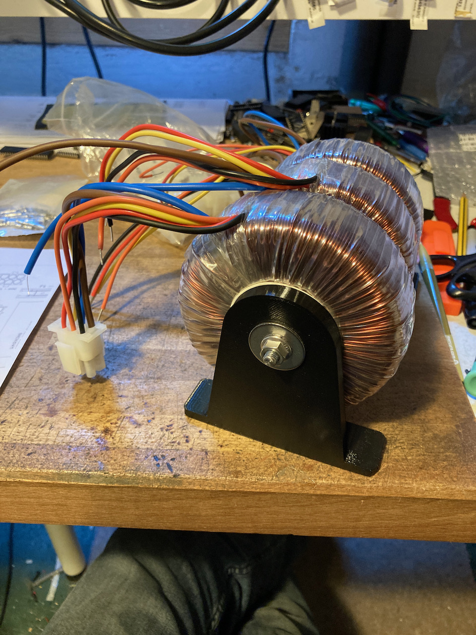
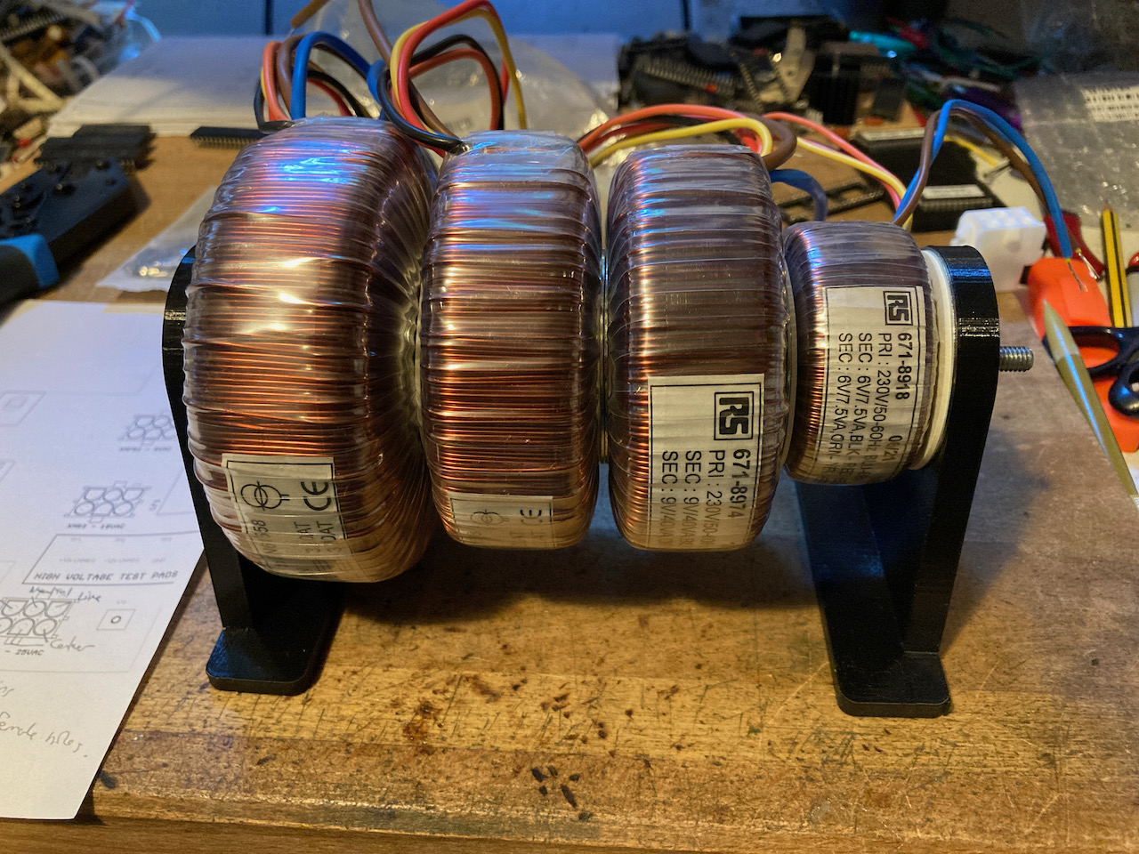
Some pics of the progress on the power brick remake

If you don't mind me asking, what are each of the coils used for? Are you using separate ones to avoid electrical transfer between boards and can you isolate the magnetic interference induced between each board?
Assume because you can't find correct transformer with multi outputs with correct voltage as original made for the specific machine, so use a few for each output
When I did similar for Toobin, I used to transformers, one had output required, I wondered if having them close to each other would cause issues?
If you want me to remove the pics of measurements to keep your thread clean on your build then just say, only for reference

Bods2021-08-05 18:15:29
When I did similar for Toobin, I used to transformers, one had output required, I wondered if having them close to each other would cause issues?
If you want me to remove the pics of measurements to keep your thread clean on your build then just say, only for reference
Bods2021-08-05 18:15:29
myPinballs
Active member
Bods said:Assume because you can't find correct transformer with multi outputs with correct voltage as original made for the specific machine, so use a few for each output
When I did similar for Toobin, I used to transformers, one had output required, I wondered if having them close to each other would cause issues?
If you want me to remove the pics of measurements to keep your thread clean on your build then just say, only for reference
No leave the measurements in there , all good, I may need some more anyway soon
")
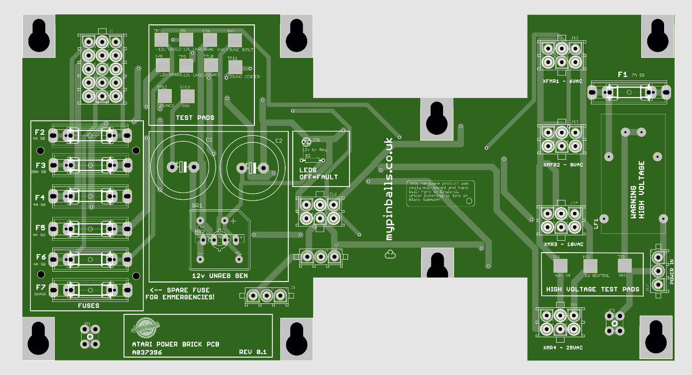
In answer to a few questions above yes the plan is to use 4 transformers (toroidal) to recreate the multi output original spec block transformer used by atari. They are double output ones of varying VA output depending on the loads needed. Some are wired parallel for the 2 outputs to double the VA, others are wired centre tapped. All this happens on the pcb and plugs to make it simple. Also, a benefit of having 4 independent transformers together mean that you could miss out one if you didn't need it for some reason, or easily change one to a differing spec for other vector monitors for example.
The research i've done suggests that mounting torordial transformers like this next to each other with the mount plates and separators and metal screw thread through the center is fine and work ok. There are metal plates in-between each one and neoprene washers. Std stuff for mounting these.
We will see how it works once the pcb prototypes are back of course though
If anyone is interested in testing one please let me know.
If I recall, the Atari B+W Vector power brick is the same as the Colour CRT version. It's the Colour Vector one that's the odd ball.
I was thinking about getting some custom transformers wound as there is a demand for colour vector bricks, but was struggling to work out the VA rating. The originals seem quite compact/small to me if you add up all the currents or go off the mains fuse rating.....it was somewhere in the 800 VA rating give or take a couple of hundred ! - Would not be cheap though to have made and best bet would be to strip one down and copy it.
I like the idea of having torroidals and the custom pcb to save chassis wiring.... Will the tracks take the rated current ? Have you gone for thicker copper ?
There are alternatives to the AR2 also.... using dc/dc convertors and such.
It's a tricky one to pin down and I like your approach on this.
ColinD said:If I recall, the Atari B+W Vector power brick is the same as the Colour CRT version. It's the Colour Vector one that's the odd ball.
Yes. They both output 30-0-30. I converted a Centi brick to colour vector by hacking in a 25-0-25 toroidal to replace the 30-0-30. Just needed a spare brick and a single toroidal. Bit of a hack job but ran fine in a Tempest without issues for years.
myPinballs
Active member
tb lilley said:ColinD said:If I recall, the Atari B+W Vector power brick is the same as the Colour CRT version. It's the Colour Vector one that's the odd ball.
Yes. They both output 30-0-30. I converted a Centi brick to colour vector by hacking in a 25-0-25 toroidal to replace the 30-0-30. Just needed a spare brick and a single toroidal. Bit of a hack job but ran fine in a Tempest without issues for years.
Yes, that's what i'm meaning with the idea of being able to swap out the monitor toroidal to suit the game the power brick runs in, as i have split out the sections of the original transformer in effect.
Also, I believe i have come up with a way to wire the 15 pin output connector so that 1 of 3 toroidals could be used at position 1 (monitor output) to suit whatever atari game you have.
Of course i need to test all this and see how things perform .
myPinballs
Active member
ColinD said:If I recall, the Atari B+W Vector power brick is the same as the Colour CRT version. It's the Colour Vector one that's the odd ball.
I was thinking about getting some custom transformers wound as there is a demand for colour vector bricks, but was struggling to work out the VA rating. The originals seem quite compact/small to me if you add up all the currents or go off the mains fuse rating.....it was somewhere in the 800 VA rating give or take a couple of hundred ! - Would not be cheap though to have made and best bet would be to strip one down and copy it.
I like the idea of having torroidals and the custom pcb to save chassis wiring.... Will the tracks take the rated current ? Have you gone for thicker copper ?
There are alternatives to the AR2 also.... using dc/dc convertors and such.
It's a tricky one to pin down and I like your approach on this.
Thanks for the reply. I'm starting with the pcb with my usual power wiring track thickness in terms of widths and ground planes etc. but standard copper weight on the board pcb itself. Its only 5 pcbs for testing with and 'burning out' etc , so whatever is learnt on testing with them will be fed back into the next few to test. I usually test with 5 at a time so i can make changes and try things before getting loads made etc.
I've already thought of something i should add to it. I didn't add a way for 115vac/120vac outputs off a primary winding so will need to work that in on the first test pcbs to run the stock light strips. I just added filtered line voltage output plugs, so here in uk 230vac/240vac . Thinking its useful to have a fixed 120vac plug, but also one of whatever your filtered line voltage is to. So you can easily run other things you might want to.
myPinballs said:tb lilley said:ColinD said:If I recall, the Atari B+W Vector power brick is the same as the Colour CRT version. It's the Colour Vector one that's the odd ball.
Yes. They both output 30-0-30. I converted a Centi brick to colour vector by hacking in a 25-0-25 toroidal to replace the 30-0-30. Just needed a spare brick and a single toroidal. Bit of a hack job but ran fine in a Tempest without issues for years.
Yes, that's what i'm meaning with the idea of being able to swap out the monitor toroidal to suit the game the power brick runs in, as i have split out the sections of the original transformer in effect.
Also, I believe i have come up with a way to wire the 15 pin output connector so that 1 of 3 toroidals could be used at position 1 (monitor output) to suit whatever atari game you have.
Of course i need to test all this and see how things perform .
If you take a standard brick, and splice in 25-0-25 to replace the 30-0-30, that brick will power any Atari vector game as it stands. A B&W vector monitor will run on 25-0-25 (a GO5 requires 28-0-28 +/-15%). Colour vector will run on 25-0-25. That might make things easier?
tb lilley2021-08-06 10:48:12
I probably massively overrated my VA calculation.... Maybe looking at around 200 VA tops plus what the monitor needs... I guess... So would 300 to 400 VA be closer ? (Without measuring the current draw on a typical machine). Maybe even less ??
If say a machine drew 1A at 240V, that's 240v / 0.8 derating = 300VA.
If I were to get some custom transformers made up (in my dreams), I'd have an extra couple of taps so that the same one could be used for all variations. It would be chassis mountable but perhaps with terminals/lugs or legs to pcb mount.
You would have to get loads made to make it viable though, so it's not going to happen.
We also need AR2 /AR3 repro's. Either original or perhaps with a modern twist.ColinD2021-08-06 19:38:18
I always thought you multiplied power by 0.8 (PF) not divided to get VA. But could’ be wrong as not googled it. Bit rusty on my ohms law

Bobbdobalina said:I always thought you multiplied power by 0.8 (PF) not divided to get VA. But could’ be wrong as not googled it. Bit rusty on my ohms law
Yes, you may be right. I just thought that transformers were inefficient and that you needed to put more in than you get out, so erred the other way !!! (which made the math work in my head for me)
Note that.... 'I just thought' can get you into all sorts of trouble !
Edit....Not been to college for nearly 30 years ish now !! I'm still learning stuff every day.
ColinD2021-08-06 20:04:32
now I’m by no means as learned as many on here, but as I understand it the 0.8 is to account for the type of load on a circuit normal type loads lighting (not fluorescent), heating etc don’t need it as it would be near 1 whereas inductive loads such as motors,fluorescent lighting(lots of) , transformers etc do.ColinD said:Bobbdobalina said:I always thought you multiplied power by 0.8 (PF) not divided to get VA. But could’ be wrong as not googled it. Bit rusty on my ohms law
Yes, you may be right. I just though that transformers were inefficient and that you needed to put more in than you get out, so erred the other way !!!
Note that.... 'I just thought' can get you into all sorts of trouble !
It also goes the other way with capacitance.
Only know this as I’m an electrician but not really into the theory side of it.
Multiplying or dividing can have a big difference. So I would check and double check any calculations.
Excellent project though and very interesting reading

Googled it and I’m wrong, you do divide it. Apologies.
Mental note google before commenting
Mental note google before commenting
The 'I just thought'... was poking fun at myself ;-) and not aimed at you.
Been a hell of a day (and quite fun for a change) chopping in a new DC 50 Amp magnet power supply on a Cyclotron and having chiller faults and stuff.... while we had patients waiting for their treatment !
I am no expert on much of this stuff myself, I just always errrm a little higher if in doubt !! - It's worked for me most of the time. Fortunately it's not a school night, so beer o clock now.
Edit... Today.... I was trying to drill out some crimps to fit to the bolts supplied with the 50A power supply as some were too small and some too big, the boss suggested smaller bolts !! - Every Day is a school day and that's why he's the boss Many ways to skin a cat ! (some of the cables were too big to go into the crimps anyway !) - Sometimes you just have to wing it... Perhaps should have just used the bigger crimps in the first place think some of it was 6mm and would not go into the yellow crimps 4mm or doubled up - When in a hurry/rush/emergency you have to make do with parts that are available to hand !
Sorry...This is all irrelevant and going off tack... I'm waiting to see how this project progresses and how the AR2 (or which ever one) hurdle is tackled next. I'm sure it will be spot on.
ColinD2021-08-06 20:53:52
Been a hell of a day (and quite fun for a change) chopping in a new DC 50 Amp magnet power supply on a Cyclotron and having chiller faults and stuff.... while we had patients waiting for their treatment !
I am no expert on much of this stuff myself, I just always errrm a little higher if in doubt !! - It's worked for me most of the time. Fortunately it's not a school night, so beer o clock now.
Edit... Today.... I was trying to drill out some crimps to fit to the bolts supplied with the 50A power supply as some were too small and some too big, the boss suggested smaller bolts !! - Every Day is a school day and that's why he's the boss
Many ways to skin a cat ! (some of the cables were too big to go into the crimps anyway !) - Sometimes you just have to wing it... Perhaps should have just used the bigger crimps in the first place think some of it was 6mm and would not go into the yellow crimps 4mm or doubled up - When in a hurry/rush/emergency you have to make do with parts that are available to hand ! Sorry...This is all irrelevant and going off tack... I'm waiting to see how this project progresses and how the AR2 (or which ever one) hurdle is tackled next. I'm sure it will be spot on.
ColinD2021-08-06 20:53:52
ColinD said:The 'I just thought'... was poking fun at myself ;-) and not aimed at you.
Been a hell of a day (and quite fun for a change) chopping in a new DC 50 Amp magnet power supply on a Cyclotron and having chiller faults and stuff.... while we had patients waiting for their treatment !
I am no expert on much of this stuff myself, I just always errrm a little higher if in doubt !! - It's worked for me most of the time. Fortunately it's not a school night, so beer o clock now.
Edit... Today.... I was trying to drill out some crimps to fit to the bolts supplied with the 50A power supply as some were too small and some too big, the boss suggested smaller bolts !! - Every Day is a school day and that's why he's the boss
Sorry...This is all irrelevant and going off tack... I'm waiting to see how this project progresses and how the AR2 (or which ever one) hurdle is tackled next. I'm sure it will be spot on.
Think that story can just relate to life in general lol… you just have to wing it and make it up as you go along and it generally works out in the end!