Asteroids Deluxe Cabaret - Scratch Build

myPinballs

Active member
Feedback
16 (100%)
Credits
658CR
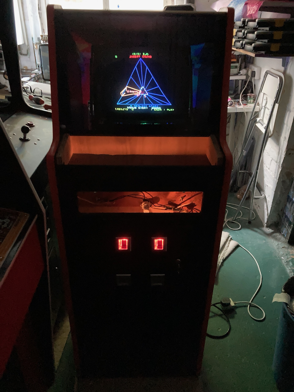
So here is my scratch 14" colour vector build after sorting out the yoke windings. Took awhile but i finally got ~1 ohm in parallel after a few attempts. I used 0.35mm wire and about 100 turns each. Picked up a barry 1.5 deflection & hv kit unused so installed that to. Designed my own neck board for a thin neck as the barry kit neck board was for a fat one!

vector_monitor_scratch_build_with_neck_board_-_1.jpeg


vector_monitor_scratch_build_new_parts_-_2.jpeg
vector_monitor_scratch_build_new_parts_-_6.jpeg


vector_monitor_scratch_build_new_parts_-_9.jpeg
 

myPinballs

Active member
Feedback
16 (100%)
Credits
658CR
Powered on and no smoke :) Had to spend a few days adjusting and also fixing some tempest board problems. This is what i had at the first proper test ru. Still needs some adjustment, but pretty happy so far. The orientation is horizontal so that i can play other game in the cabinet. Asteroids Deluxe and Major Havoc. (I actually had to fix my tempest board again as i had a dac issue that cropped up after a day of it working fine. Waiting for those parts to arrive)

vector_monitor_first_run_-_1.jpeg
vector_monitor_first_run_-_4.jpeg
vector_monitor_first_run_-_8.jpeg
vector_monitor_first_run_-_9.jpeg
 

Retroman839

Senior Member
vacBacker
Feedback
12 (100%)
Credits
7,031CR
smiley32.gif
It’s like fireworks …
smiley1.gif

Well done!! Looks great…

There was A guy making just the Atari card.. screen bezels
That was about 2 years ago though

As you’ve made This much though I think you can probably
Handle a little bit of origami

That’s Going great pinballs..
 

myPinballs

Active member
Feedback
16 (100%)
Credits
658CR
Update on the control panel build. I got my prototype panels in to test fit etc. Pretty pleased with the first attempt. A few things to tweak i think but it fits very nicely.

Buttons and holes positioned so you can play tempest and asteroids pretty easily as mentioned above.

control_panel_metal_-_1.jpeg
control_panel_metal_-_2.jpeg
control_panel_metal_-_3.jpeg


myPinballs2022-08-17 17:40:16
 

qjuk

Active member
vacBacker
Feedback
47 (98%)
Credits
1,655CR
This build looks really nice
smiley1.gif


Can I ask what tube and yoke you used for the vector monitor?

I’ve also got Barry’s kit but I’m struggling to find a donor 14” tube with a suitable yolk to wind back.

Also, did you have to adjust the B+ as Barry recommended I lower it a bit for a 14” tube?
 

myPinballs

Active member
Feedback
16 (100%)
Credits
658CR
qjuk said:
This build looks really nice 
smiley1.gif


Can I ask what tube and yoke you used for the vector monitor?

I’ve also got Barry’s kit but I’m struggling to find a donor 14” tube with a suitable yolk to wind back.

Also, did you have to adjust the B+ as Barry recommended I lower it a bit for a 14” tube?

I will dig out the details on the tube I used. It was from a Phillips 14” tv with built in video player! Tubes in consumer tvs are so much cleaner and crisp compared to old arcade crts! Just not on as much I think

I produced my own neck board to use with the Barry kit as the tube neck was a small type. I have these available should you need onemyPinballs2022-08-17 22:06:02
 

myPinballs

Active member
Feedback
16 (100%)
Credits
658CR
Some updates on this project. Been populating the control panel with some test parts to see how it works. All seems good. I have the full set of tempest controls wired up now. There is also space for the asteroids controls without any issues afaics

I have some new control panel metals to get made now with a couple of minor changes etc. These stainless steel ones have worked out well. Also got to get some new leaf switch and new buttons. Deciding whether to have white & black or maybe some purple in there to

IMG_5487_Large.jpeg
IMG_5529_Large.jpeg


myPinballs2023-01-26 12:36:32
 

qjuk

Active member
vacBacker
Feedback
47 (98%)
Credits
1,655CR
You’ve done a good job there with the build
smiley20.gif


It looks like you’ve also successfully managed to repro my Tempest Spinner pcb
smiley2.gif

I just wanted to ask, does the repro pcb work flawlessly? The reason why I am asking this is because I’ve just recently repro’d an Arkanoid spinner pcb and it does work, however I’m getting a slight judder with the vaus if I slowly move it left or right. I’m thinking that maybe the opto sensors need to be at a slight angle (where as I put both opto’s parallel to each other). I notice the Tempest opto is also slightly angled too and just wondered if you have the same slight judder movement with the claw onscreen as well?
 

myPinballs

Active member
Feedback
16 (100%)
Credits
658CR
qjuk said:
You’ve done a good job there with the build
smiley20.gif


It looks like you’ve also successfully managed to repro my Tempest Spinner pcb
smiley2.gif

I just wanted to ask, does the repro pcb work flawlessly? The reason why I am asking this is because I’ve just recently repro’d an Arkanoid spinner pcb and it does work, however I’m getting a slight judder with the vaus if I slowly move it left or right. I’m thinking that maybe the opto sensors need to be at a slight angle (where as I put both opto’s parallel to each other). I notice the Tempest opto is also slightly angled too and just wondered if you have the same slight judder movement with the claw onscreen as well?

That was going to be my next message. You beat me to it. I'm still working on them, but have a first revision made and working ok. Only got it together last night. (I also need to return your original board and supply you with some spare blanks). I'm basically waiting for my next version to arrive as i had to make some changes, but the first rev ones are working ok and i haven't noticed anything glitching or juddering yet. The 2 optos are in parallel on mine to. I will shoot a quick vid to compare.
 

myPinballs

Active member
Feedback
16 (100%)
Credits
658CR
Infurious said:
Takes a while for this, but really coming along.

Have you thought about the decals, CPO, etc...?

Yes, i am going to be asking mr @muddymusic for some help here i think on the cpo. :) I quite fancy a combined version of the asteroids cabaret cpo but with some tempest stuff on it to for the spinner area.

Yes it is a long term project, but i am hoping to offer all the wood cutting plans, monitor info, pcbs and the cpo metal as a barebones kit once its all completed for others to make one if they fancy it.

myPinballs2023-01-26 18:38:30
 

myPinballs

Active member
Feedback
16 (100%)
Credits
658CR
qjuk said:
You’ve done a good job there with the build
smiley20.gif


It looks like you’ve also successfully managed to repro my Tempest Spinner pcb
smiley2.gif

I just wanted to ask, does the repro pcb work flawlessly? The reason why I am asking this is because I’ve just recently repro’d an Arkanoid spinner pcb and it does work, however I’m getting a slight judder with the vaus if I slowly move it left or right. I’m thinking that maybe the opto sensors need to be at a slight angle (where as I put both opto’s parallel to each other). I notice the Tempest opto is also slightly angled too and just wondered if you have the same slight judder movement with the claw onscreen as well?

Played a good few game today and the optos are working great. No judder just silky smoothness. I'll pm you. Maybe the optos you are using are not good.
 

myPinballs

Active member
Feedback
16 (100%)
Credits
658CR
Finally got chance to finish the next revision of my Atari vector power brick remake pcbs. A few improvements over the photo rev 1 boards including 12v terminal & fuses for both sides of the 25vac monitor power output.

Part of the delay with making these has been that I wanted to test for an extended period of time, longer soak test etc to make sure all parts are parts a upto the task of being used and not used etc Turned on and off loads etc long on, short on and off etc. I have been testing in my scratch build Atari cabaret for quite awhile now as well as powering and testing other vector monitors with it. ALL GOOD so far.. :)

atari power brick v0.3.png
 

myPinballs

Active member
Feedback
16 (100%)
Credits
658CR
Atari power brick update and more progress. The final piece of the puzzle for this new board. I now have 120v output working from regular 240vac input, as per the original design. I needed to use a different toroidal for one of the sections, so i picked the lighting one as the 120vac is also for lighting (marquee tube). Now i have my original marquee lamp board working perfectly at 120vac.

IMG_7574.JPGIMG_7575.JPGIMG_7576.JPG
 

ArcadePCB

User
vacBacker
Credits
509CR
Great job.
Can you tell who's making your control panel? I'm not sure watching your photos - is it a true radius at the front or are these multiple bends? On one photo, it seems to be a real radius, on the other it doesn't.
I've figured out it's not so easy to find someone who's able to make (and wants to make) a control panel. It seems to be the radius on the front why companies often refuse making a control panel.
 

myPinballs

Active member
Feedback
16 (100%)
Credits
658CR
Great job.
Can you tell who's making your control panel? I'm not sure watching your photos - is it a true radius at the front or are these multiple bends? On one photo, it seems to be a real radius, on the other it doesn't.
I've figured out it's not so easy to find someone who's able to make (and wants to make) a control panel. It seems to be the radius on the front why companies often refuse making a control panel.
Its multiple bends but hardly noticeable. The file was sent with a smooth bend and this is how they made it. Its just a prototype though and i'm getting some updated ones made soon, so i will ask about this process.
 
Top