Asteroids sound problem

minwah

Active member
Feedback
3 (100%)
Credits
238CR
I have just re-measured the AC volts, and they are much the same as my original readings:

Pin 6 & 7 = 2.7 VAC (should be 36)
Pin 8 & 9 = 11.83 VAC (should be 6.3)
Pin 11 & 13 = 17.3 VAC (should be 65)

So as before I don't really know what these mean...since everything basically powers up I am not sure whether to believe the figures. Then again, I don't see how two different meters would give false readings.

If the readings are correct does this mean something is wrong with the transformer? AC comes straight from the transformer right? Do transformers even go wrong?
 

Zektor

Active member
vacBacker
Feedback
4 (100%)
Credits
312CR
I'd say it's more likely you have the pin numbers wrong. Measure at the multipin connector at the transformer and write the colour of the wire down with the pin number. You can
Then look at the wiring diagram on the schematic sheet to see if you have it right.
 

Purity

The Oracle
vacBacker
Feedback
17 (100%)
Credits
2,999CR
I always get confused with the pin numbering.

This was posted by Level42 on DLF. Maybe it would help?

Atari_Power_Brick_Voltages.png_thumb.png
 

minwah

Active member
Feedback
3 (100%)
Credits
238CR
Purity said:
I always get confused with the pin numbering.

Thanks guys, that was my first thought too. But I have checked and the orientation for J5 is the same in that pic as it is when looking through the back door of the cabinet with the PSU in place, so I'm pretty sure I am doing it right!
 

minwah

Active member
Feedback
3 (100%)
Credits
238CR
Zektor said:
Measure at the multipin connector at the transformer and write the colour of the wire down with the pin number. You can
Then look at the wiring diagram on the schematic sheet to see if you have it right.

Good tip - I will do this to double check, thanks!
 

guddler

Busting vectors like it's 1982!
vacBacker
Feedback
10 (100%)
Credits
4,058CR
Yeah, but hang on - am I going to be the one to point out that the diagram is confusing in itself?? It simply says "Atari Power Brick Connectors" It doesn't say if the diagram is showing the receptacles in the brick, or the plugs that go into the receptacles in that brick - in which case it would all be reversed.

I've been following the thread and I think it's highly likely that there is confusion in what is being measured and how it's being measured, but we can't guarantee it for sure without going round and measuring it for ourselves.

I DO indeed have a perfectly working Asteroids but firstly, no more pulling my own machines out to test other peoples stuff. That's how I've managed to kill my Tron, AND my Robotron, AND, I seem to remember my Asteroids at one point but I quickly fixed that, and on top of that, me reporting back that I get the values shown in the manual isn't really going to help anyway. Oh, and my shed isn't remotely tidy so I can't really get to it without clearing up at the moment!

I keep telling myself I'll never pull my own stuff apart to test other peoples kit. Usually by plugging someone else's PCB into my working cab to test it. Yet I still do it, time and time again and break my own stuff.

Anyway, back on topic. I may have already said this, so apologies if I have, but is anyone that knows for 100% sure how to do it, close enough to go round and check the voltages, ruling both the power brick and AR board IN or OUT of the problem once and for all?

I've never known an Asteroids sound fault to be anything other than easy (to someone who knows how to fix PCBs, and AR boards) but we need to ensure good power once and for all first.

 

P-Man

International man of mystery
Feedback
4 (100%)
Credits
1,273CR
pin numbers are fixed on the housings, so it doesn't matter what the diagram describes, the numbers are on the plug/housing itself, you can't mix them up (but this user might somehow be doing so).
 

minwah

Active member
Feedback
3 (100%)
Credits
238CR
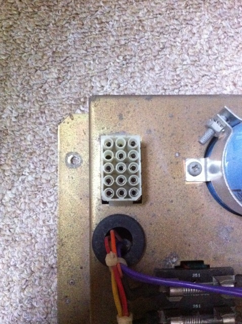
image.jpg


Ok so I am getting somewhere...as guessed I was had the pins wrong. Lookong at the female connector as per the pic, I was using these pin numbers:

15 14 13
12 11 10
09 08 07
06 05 04
03 02 01

The correct numbering is as follows:

13 14 15
10 11 12
07 08 09
04 05 06
01 02 03

I now have these readings:

1/2/3 & 4 = 14VDC (10.3)
6 & 7 = 37.73VAC (36)
8 & 9 = 7.15VAC (6.3)
11 & 13 = 67.8VAC (65)

So these all look good!
smiley4.gif


I've had a quick look at the AR board and it looks like it has had some work done on it at some point. The molex connector pins and both of the TDA2002's have been resoldered, maybe replaced? Are there any checks I can do on this board, other than testing the 5V (which is good)?

Thanks for your patience with this!
 
Top