You are using an out of date browser. It may not display this or other websites correctly.
You should upgrade or use an alternative browser.
You should upgrade or use an alternative browser.
Atari System 2 PCB Repair - Paperboy
- Thread starter Purity
- Start date
Symptom
Paperboy CPU board - Music distorted
Fix
Initially I thought this was an issue with the LM324 @ 9J/K. I tested pins 10 with an audio probe and the sound was good, but was distorted on pins 8 and 9. I isolated the pin 8 output by lifting the leg of the cap @ C64 and used Phil's audio probe on the other leg of the cap. The music was still distorted.
So I replaced the Op Amp, but still had the same issues
The problem could only be in a small number of components and in the 2.5v adjust section.
I measured the voltage at one end of resistor R105 and got 5 volts as expected. I then measured the other side expecting something like 2.5v though a 1K resistor, but got 0.64v, so this is where the problem was.
I had a look at components R105, R104 and C91, and all of them had corroded legs so decided to replace them all, and sound was now as expected

Purity2019-02-10 16:26:38
Paperboy CPU board - Music distorted
Fix
Initially I thought this was an issue with the LM324 @ 9J/K. I tested pins 10 with an audio probe and the sound was good, but was distorted on pins 8 and 9. I isolated the pin 8 output by lifting the leg of the cap @ C64 and used Phil's audio probe on the other leg of the cap. The music was still distorted.
So I replaced the Op Amp, but still had the same issues
The problem could only be in a small number of components and in the 2.5v adjust section.
I measured the voltage at one end of resistor R105 and got 5 volts as expected. I then measured the other side expecting something like 2.5v though a 1K resistor, but got 0.64v, so this is where the problem was.
I had a look at components R105, R104 and C91, and all of them had corroded legs so decided to replace them all, and sound was now as expected
Purity2019-02-10 16:26:38
For anyone else that might setup a pcb on a test bench, it seems that +12v DC is fine for both "Power OK", and as a substitute for +15v. Obviously I wouldn't recommend doing this long term. It is just for working on the PCB out of the cab, and without the need for an AR3 or brick. You can run everything off a switcher.
I also added a small 5v amp that connects to the connector at J15 on the CPU board, so I can hear the sound.
In order to get sound and for inputs to work you need to have -5 volts which is derived from -15v on the PCB. To just use a switcher on a test bench you can clip -5v to one end of the capacitor marked C140 and this works fine.
To output the display you can use an Acorn CRT monitor (AFK18 or AFK52) that allows for medium res or an LCD like a NEC AccuSync LCD 1770 nx
I also found that for the different monitors you also had to put inline resistors on the Red/Green/Blue to get the perfect image.
For the NEC - 270 Ohms
For the Acorn - 33 Ohms
Ace` said:Good info, how does the GBS-8220 upscaler cope if you haven't got one of those monitors? I haven't had to hook up anything medium resolution yet.
They work, but they are not great. On mine the picture started off ok, but within about 5 mins, the whole screen gradually turned white to the point that you can't see anything anymore. Making adjustments made no difference.
I bought the NEC LCD monitor on eBay for £18 delivered, and noticed that there are still some for sale. If you are serious about repairing medium res games I'd forget the upscaler and get one of those monitors, they are superb
Symptom
Paperboy CPU board - Speech running at twice speed
Possible Fix
This one took me quite a while to figure out.
I checked pin 8 on the Speech chip with an audio probe and the speech was also twice as fast at this point, so confirming that the fault was somewhere before the LM324 amp. I thought it might be a fault with the speech chip itself but it was good, and all voltages to it were fine.
Obviously this was a timing issue, but I had no clue where to look, as it wasn't clear to me on the schematics how the clk circuit in the speech section was all tied together.
I brought up the datasheet for the TMS5220C and noted all the pins used by Paperboy. The one that really stuck out for me was the OSC @ pin 6 which was the oscillator input, as it looked like the clk pin at pin 3 was not used by Paperboy.
The datasheet also mentioned that the oscillator needs to run at 640khz.
So I got the scope out and connected to pin 6 and measured the wave and it was reporting as 1.25Mhz, which when converting to Khz is twice as fast, so I was on to something.
I then looked in the Tclk, and T1clk section with the scope taking measurements and this was still reporting as 1.25Mhz, to the LS163 @ 4D. I confirmed that both pin 2 was 5Mhz and pin 12 was 1.25Mhz.
At this point I had a look at a working Speech board, and it was 1.25Mhz @ pin 12 so this was correct. However it then went to the LS74 @ 4C/D. This had a clock pin @ pin 11 from the LS163 which was 1.25Mhz, but the output pins @ 8, 9, and data 12 showed 640Mhz, whereas my faulty board was showing 1.25Mhz at all these pins!
This would conclude that the fault was at the 74LS74 because this should be dividing the clock signal and it is not doing so. I will change this and see what happens!
Purity2019-02-15 22:29:03
The fault with the speech above actually turned out to be a fault at the chip before the 74LS74 @ 4C/D.
The 163 at 5D had a missing 1.5mhz signal @ pins 9 and 15, and also double the speed @ pin 13 (2.5mhz instead of 1.25mhz)
Replacing this chip fixed the issue
Two boardsets now fixed

Purity2019-02-16 15:26:15
The 163 at 5D had a missing 1.5mhz signal @ pins 9 and 15, and also double the speed @ pin 13 (2.5mhz instead of 1.25mhz)
Replacing this chip fixed the issue
Two boardsets now fixed
Purity2019-02-16 15:26:15
Russian Clone CPU - KP1807BM1
Now that I had two working boardsets I decided to see if the Russian clone chip works as a replacement for the T11 CPU
Although the chip does work - i.e. the game boots and plays, and all diagnostics check out, I found that it is unstable and the PCB crashes on a regular basis
For that reason I suggest that an original T11 CPU is found if you need to substitute the CPU
Purity2019-02-16 15:31:18
The AR3 can handle a max of 10A @5v from memory, but I seem to remember the max current draw was more like 7A from these boards.
What I did notice is that a typical switcher has a poor voltage regulation of about +-0.3v whilst the venerable AR3 is more like 0.05v. A major reason why I recommend people don't install SMPS.
What I did notice is that a typical switcher has a poor voltage regulation of about +-0.3v whilst the venerable AR3 is more like 0.05v. A major reason why I recommend people don't install SMPS.
Symptom
Paperboy CPU board - Game would crash at the very start of trying to play Monday. Gradually got worse and then was stuck on the test screen.
Fix
244 Pin 17 @ 2F was stuck low. Traced this back to faulty resistors and caps @ R155/156, C112/C113. Replaced all of them as they looked like they had some corrosion on their legs. Game booted as normal and played fine.
Symptom
Paperboy CPU
board - Game sound randomly worked. Sometimes music worked then died. Sometimes Pokey's worked then died. Speech never worked.
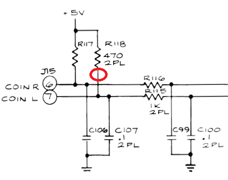
Coin inputs would display on test screen randomly, and be stuck
Game sound would die during game, no speech. Game would also crash and reset randomly.
Fix
I guessed that this was likely a voltage issue and failure of -5v somewhere. The indication of this was the random display of coin inputs on the test screen and loss of sound. Looking at the -5v section I found a 1K resistor @ R164 which looked faulty, the voltage past the resistor looked too high. I replaced the resistor and the game sounds all worked, no coin inputs being stuck or displayed, and no crashing.
Paperboy CPU
board - Game sound randomly worked. Sometimes music worked then died. Sometimes Pokey's worked then died. Speech never worked.
Coin inputs would display on test screen randomly, and be stuck
Game sound would die during game, no speech. Game would also crash and reset randomly.
Fix
I guessed that this was likely a voltage issue and failure of -5v somewhere. The indication of this was the random display of coin inputs on the test screen and loss of sound. Looking at the -5v section I found a 1K resistor @ R164 which looked faulty, the voltage past the resistor looked too high. I replaced the resistor and the game sounds all worked, no coin inputs being stuck or displayed, and no crashing.
bernardmerguez
Newbie
- Credits
- 7CR
They accept pretty much anything if you set the parameters properly.Purity said:They work, but they are not great. On mine the picture started off ok, but within about 5 mins, the whole screen gradually turned white to the point that you can't see anything anymore. Making adjustments made no difference.
What you describe is a well known issue, just adjust clamp st = 56, clamp sp = 61.
bernardmerguez2020-04-16 13:14:04
bernardmerguez
Newbie
- Credits
- 7CR
You statement was wrong.Purity said:I just bought a couple of Med Res LCD screens and they work great. No adaptor required
My answer is useful to others.
Don't be too frustrated to have failed.bernardmerguez2020-04-16 13:40:24
bernardmerguez said:You statement was wrong.Purity said:I just bought a couple of Med Res LCD screens and they work great. No adaptor required
My answer is useful to others.
Don't be too frustrated to have failed.
??? He was not being rude, I think you misread his reply.