Dead Gauntlet - Need Help

Credits
9CR
I've just started work on my Atari Gauntlet. This was sold as fully-working, but died when moved for transport. I suspect something's worked loose.

Upon power-up:
  • Monitor fires up with a white/grey screen.
  • No game activity. Nothing heard when credits added.
  • Red LED lit on the game board.
Before I dive in with the multi-meter and logic probe, I've noticed that the voltage selector isn't plugged into anything. I can't find anything about this in the manuals. Should it be plugged in? [Picture below]

Gaultlet_1.jpg


All the best,

Simon
 

karlcdoe

Active member
vacBacker
Feedback
8 (100%)
Credits
887CR
I'm pretty sure it is plugged in. Isn't it like one or two plugs tied together with cable ties or something and I'm guessing the one with the brown wires is currently selected. I suspect you wouldn't get a white screen on the moniotr or an LED lit on the pcb without a selection plug in, if in doubt check the operators manual which I'm sure is online somewhere.

I'd check for +5v etc on the logic board and try powering up in test mode. After that I guess you have to check for CPU activity/watchdog reset, etc, etc as it sounds like it's not booting.

I had a JAMMA'd Gauntlet somewhere that I managed to get to boot so it can't be that 'fussy'
smiley36.gif

karlcdoe2012-05-30 09:55:11
 
Credits
9CR
Thanks for the replies.

Unplugging and plugging in all connectors has brough the game to life.

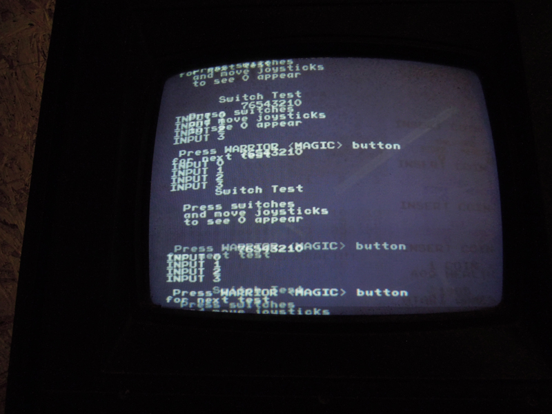
The game will start (but quickly resets) and I can get part-way through the diagnotics (and some of the controllers need work).

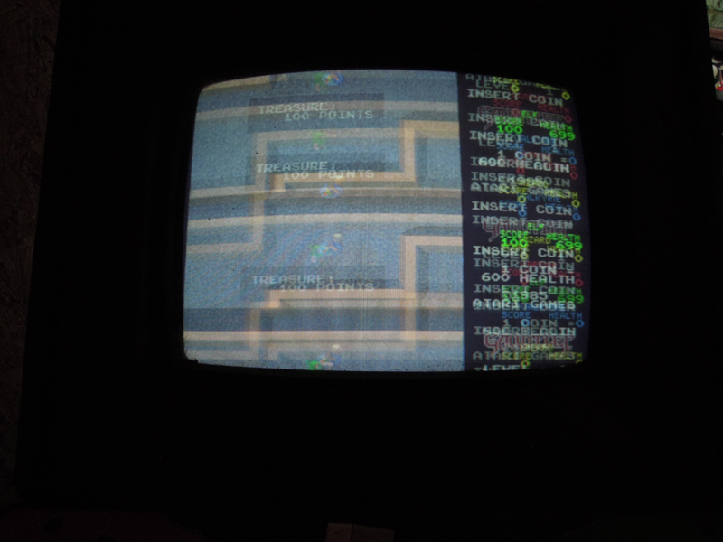
But the image is displayed three times:

g2.JPG


g1.JPG


Does anyone quickly know whether this is a monitor or board fault?

Incidentally what are the name of the single-row connectors used to connect the video cable from the board to the monitor. I'd like to order one so I can rig up a test cable to a spare CRT.

All the best,

Simon
 

Zabanitu

User
Credits
330CR
usually when you have things displayed twice or more could be a bad 74ls161 or 74ls163.

try to piggyback them and see what changes.

also try to adjust +5V voltage.

Bye
 

trm

Who loves you, and who do you love?
Feedback
2 (100%)
Credits
2,877CR
Another vote for poor sync adjust. The tile map looks just about right so I'm guessing the game is alive.

If you still want the connector details can you upload a pic of them?

Cheers
 

karlcdoe

Active member
vacBacker
Feedback
8 (100%)
Credits
887CR
it looks like a sync issue on the monitor to me which should just require adjustment (if not a possible chassis fault) or equally likely there is a bad connection on those crappy header pins Atari used for the monitor to game pcb connection.
 
Credits
9CR
Thanks for all the replies.

Tried adjusting the sync on the monitor and - it worked.

Left the game powered up for about ten minutes and from then on it played fine.
smiley1.gif
Tried again today - it seems to require about five minutes to warm up - the board keeps reseting until suddenly it becomes stable.

Voltage on board is a constant 4.95V - even during the five minutes "warm up."

However... and more worryingly... have tried it again and I'm now getting shocks off the exposed metalwork and the game is dead. It's just a "tingle" but worrying. Will check that everything is earthed correctly. It's also very humid today.

So, two steps forward, one step back.

All the best,

Simon
 
Credits
9CR
I've slept on this and gone right back to basics. I've now measured the voltages at the plug:

L-N: 230V

L-E: 108V

N-E: 66V

Horrible.

I'm going to call in an electrican to sort out the supply to the arcade before doing anything else.

I'll let you know....

All the best,

Simon
 
Credits
9CR
The saga continues...

I'm now running the game from a different power supply. No more shocks from any exposed wiring.

Game is dead. Monitor shows a static image of multicoloured squares.

  • Checked all voltages on the regulator board. All voltages present and OK. +5V is a little low at 4.95V - adjusted it up to +5V after finding the pot covered with gel - no change.
  • Checked voltages on game board - +5V OK. LED lit.
  • Decided to check pins on the CPU. RESET* and HALT* are low. Trace back on schematics. SYSRES* is low.
  • Strap the watchdog circuit. No change - RESET* is high but HALT* is low.
  • Check 7407 at 13K. SYSRES* is at 4.20V at pin 11 and the output is 0.3V.
  • So... bad 7404. (I think!)
And this is where I attempt to solder something for the first time in decades. And have made a mess of it.

I followed the tips in this video (http://www.youtube.com/watch?v=3XeEn2ENYj0). Added new solder to existing 7407 pins on solder side of board - and used at 18W iron with chisel tip and solder-sucker to remove solder. This takes about half an hour but in the end I get the solder out.

7407 is still solid in the PCB. Attempt to remove solder from component side using braid. Only a little is removed.

Attempt to add more solder to the solder side of the board and suck it out again. Only succeeded in refilling some of the holes which are now being very stubborn.

Find an old 50W solder station with pointed tip. Decide that it's probably too powerful. I've now spent 90 minutes trying to remove that 7407.

So, there must be an easier and quicker way to do this?

As for the 7407, I'm thinking of sawing through the legs with a Dremel, melting the solder on the component side and using pliers to remove the rest of the legs. Would this work?

All the best,

Simon

 

DanP

Administrator
Staff member
vacBacker
Feedback
5 (100%)
Credits
2,232CR
Snipping the legs is valid if you're sure the IC is dead (or you don't want to keep it). Best off using some small long nose clippers (or nail clippers in a pinch) over a dremel. Just take it gently with pulling the pins out, don't force anything and you should be fine.

Dan
 

Zabanitu

User
Credits
330CR
before stripping the IC, try to change the capacitor near it (should be around 47uF i think).
the cap is reponsible for the time costant wich then resets the board.
if the cap is damaged it won't charge and the IC will not invert the signal to reset the board.
have a look at the schematics to understand what i mean.
Zabanitu2012-07-05 19:58:45
 
Credits
9CR
Many thanks to all who replied.

Here's the schematic for the part of the board I've been working on:

gschem1.jpg


/SYSRES was high and at 4.15V. The signal's then split through 13K which is a 7404.

Following through pins 10 and 11, the voltage was measured at 4.95V and was connected to the CPU's /HALT signal. No problem there.

However, following through pins 12 and 13, the voltage was measured at 0.93V and was connected to the CPU's /RESET signal. Problem.

I replaced the 7404 at 13K but it made no difference.

Then, as a temporary check, I bent out the RESET pin of the CPU and tied it high by a separate wire. Success! Game now fully works.

I suspect there's a short to ground somewhere on the part of the circuit highlighted yellow? Or could the resistor at RN8 failed in some way?

It's a bodge but at least the game is working. But I'd still like any ideas as to what the real problem is so it can be fixed properly.

All the best,

Simon
 

cliff_poole

Active member
vacBacker
Feedback
6 (100%)
Credits
1,069CR
The 7404 has open collector outputs so your circuit there has a resistor network "RN8" to pull the outputs high. Did you put the new 7404 back in a socket ?. If you did, with the power off, take out the chip and measure the resistance between pin 12 of the socket and the +5v line, it should measure around 470 ohms.
 
Top