
You are using an out of date browser. It may not display this or other websites correctly.
You should upgrade or use an alternative browser.
You should upgrade or use an alternative browser.
Power Supply Problem
- Thread starter Woodstock
- Start date

Hi,
I have replaced all of the caps now and also resolved a few poorly soldered joints. PSU is back together again but I am wary about putting it back in my cab until I have tested the voltages. I've seen some comments about loading up a PSU outside of the cap to allow voltages to be tested but not sure how to do this and couldn't find further info.
Any comments or tips would be greatly appreciated! Ready to fire it up and see if it makes my R-type bootleg game run....
Thanks!
I have replaced all of the caps now and also resolved a few poorly soldered joints. PSU is back together again but I am wary about putting it back in my cab until I have tested the voltages. I've seen some comments about loading up a PSU outside of the cap to allow voltages to be tested but not sure how to do this and couldn't find further info.
Any comments or tips would be greatly appreciated! Ready to fire it up and see if it makes my R-type bootleg game run....
Thanks!
silverfox0786
Beware the Hillman
you see the blue wires (Power Switch)
wire it in like that put the 240 input wires in and then you can test all out put voltages


silverfox07862016-04-14 15:15:27
wire it in like that put the 240 input wires in and then you can test all out put voltages
silverfox07862016-04-14 15:15:27
yes that's the pinouts!
I loaded the monitor power (110v) with a 240v lamp, and then loaded the 12v supply and the 5v supply with lamps to make sure it worked as it should before reassembling. the power supply's in the background make up the input supply voltage as I was not at this point wanting to connect them directly to the national grid! this was so if anything was not right the input current would be well limited and not blow it all up as raw mains would do as these psu's had a lot wrong with them.
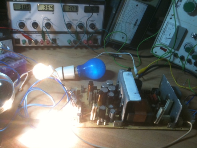
I loaded the monitor power (110v) with a 240v lamp, and then loaded the 12v supply and the 5v supply with lamps to make sure it worked as it should before reassembling. the power supply's in the background make up the input supply voltage as I was not at this point wanting to connect them directly to the national grid! this was so if anything was not right the input current would be well limited and not blow it all up as raw mains would do as these psu's had a lot wrong with them.
Hi,
My PSU was already wired with the "switch" in the configuration that was shown in the image above, so I went straight to testing the outputs. I suppose this is because my machine doesn't have an on/off switch, I just plug it in or unplug it.
I tested my output +5v supply as that is the only feed that is supplied by the PSU, the monitor is supplied by a transformer. I have put a picture in below as I'm not sure if this is a standard set up?
Anyway, i got the following results: I was able to turn the +5v up to 5.2v, which is what I need for the bootleg PCB and when I measure at the output from the PSU, that is what I get, 5.2v. However, when I plug in the PSU and test the voltage on the CPU (on one of the corner legs of a chip), it has dropped to 4.6v, does this sound right?
Also, you will note below that the monitor is supplied directly from the transformer in the bottom left corner of the picture. I have measured the voltage that is going up to the monitor and it is 104v.
Should have said, the game still doesn't work as it should. A lot of vertical lines on the monitor that obscure the picture and "hidden" background that you crash your ship into because you can't see it.
Thanks for any pointers! BTW, just to reiterate, my double dragon 1&2 PCB's work fine.
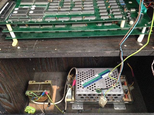
My PSU was already wired with the "switch" in the configuration that was shown in the image above, so I went straight to testing the outputs. I suppose this is because my machine doesn't have an on/off switch, I just plug it in or unplug it.
I tested my output +5v supply as that is the only feed that is supplied by the PSU, the monitor is supplied by a transformer. I have put a picture in below as I'm not sure if this is a standard set up?
Anyway, i got the following results: I was able to turn the +5v up to 5.2v, which is what I need for the bootleg PCB and when I measure at the output from the PSU, that is what I get, 5.2v. However, when I plug in the PSU and test the voltage on the CPU (on one of the corner legs of a chip), it has dropped to 4.6v, does this sound right?
Also, you will note below that the monitor is supplied directly from the transformer in the bottom left corner of the picture. I have measured the voltage that is going up to the monitor and it is 104v.
Should have said, the game still doesn't work as it should. A lot of vertical lines on the monitor that obscure the picture and "hidden" background that you crash your ship into because you can't see it.
Thanks for any pointers! BTW, just to reiterate, my double dragon 1&2 PCB's work fine.
A voltage drop of 0.6V is rather high. 0.2 - 0.3V is what you would normally expect.
You could try to find the cause of that voltage drop, by starting where the power arrives and measuring further and further away from that point. Sometimes, soldering a wire from one end of the pcb to the other can resolve voltage drops.
You could try to find the cause of that voltage drop, by starting where the power arrives and measuring further and further away from that point. Sometimes, soldering a wire from one end of the pcb to the other can resolve voltage drops.
just load the 5v with a bulb (6v 10 watt ) or something like that so it draws a couple of amps then measure the voltage across the bulb, it may well be you have other troubles with the psu and its not regulating and changing under load. At this point you cannot tell if the psu is faulty or the power wires to the board are not good enough. I always load psu's up with a good load after repairing them, it is the only way to test them without blowing up boards
Hi chaps,
Thanks for your pointers above.
I have done the following:
Checked the output from the PSU = 5.2v
Checked the output from the PSU with a bulb inline across the outlet = 5.2v
Checked at the edge connector (edge connector not connected to the PCB) = 5.2v
Checked at the edge connector (edge connector connected to the PCB) = 4.7v
So, it seems that as soon as I connect the power supply to a significant load, the voltage drops... Thought about fitting a new wire between the PSU and the edge connector but don't think this is the problem.
Thanks for your pointers above.
I have done the following:
Checked the output from the PSU = 5.2v
Checked the output from the PSU with a bulb inline across the outlet = 5.2v
Checked at the edge connector (edge connector not connected to the PCB) = 5.2v
Checked at the edge connector (edge connector connected to the PCB) = 4.7v
So, it seems that as soon as I connect the power supply to a significant load, the voltage drops... Thought about fitting a new wire between the PSU and the edge connector but don't think this is the problem.
Just as an update, putting two new supply wires from the PSU to the edge connector has helped. Now getting 5.2V up to the edge connector and just lest than this (5.14V) when testing on the end legs of some of the chips. Game still no better, so some head scracting going on...

Yes, I think you are right. I just reseated all of the chips to make sure they were all ok. However, if anything the picture on the monitor is worse now, with the top half of the screen with no picture now
 I'm not having any luck with this... I think I will take break for a few hours and then start reading up about what can cause the image that is being sent to the screen to be disrupted.
Just would like to start by saying thanks very much to those of you that have responded and given me guidance and I hope you continue to find the patience and time to share your knowledge.
Anyway, with that said, I have done a detailed inspection of the PCB board and found three obvious faults:
1) I put a chip back in backwards, chalk that down to inexperience and lack of attention to detail. Now corrected, hope it didn't cause the chip to become damaged.
2) There is a non-socketed chip with a missing leg and a resistor soldered in across two of the legs. However, I'm not sure the missing leg is deliberate or if the resistor being added is some kind of bodge repair to accommodate the missing leg? Also, if I was to replace the chip would I need to solder in a resistor the same as the current set up?
3) A component is damaged. Not sure what it is but if anyone out there knows, please give me a shout. It obviously needs to be replaced.
A couple of pics to follow. As always, all help and comments are much appreciated.
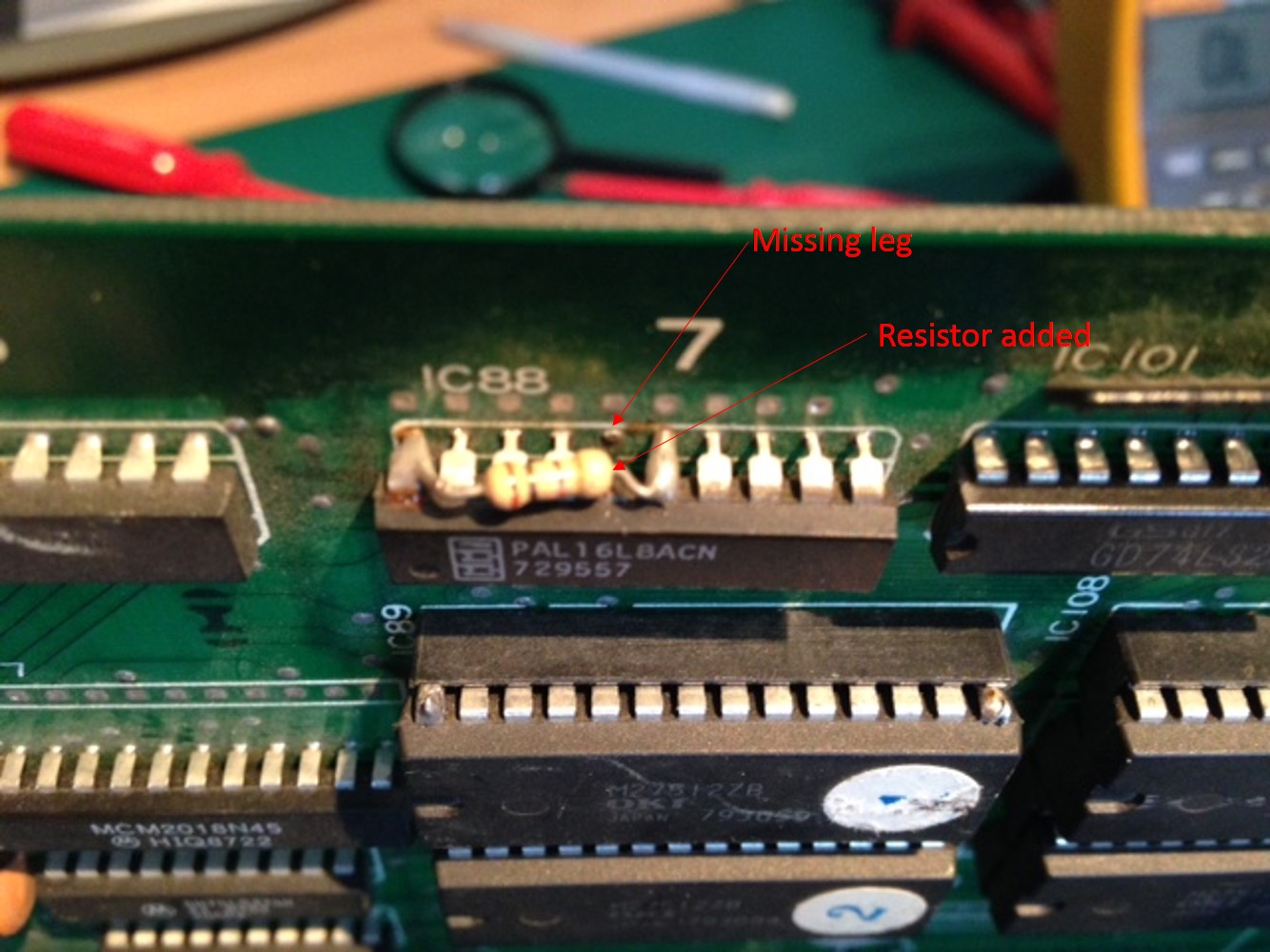

Anyway, with that said, I have done a detailed inspection of the PCB board and found three obvious faults:
1) I put a chip back in backwards, chalk that down to inexperience and lack of attention to detail. Now corrected, hope it didn't cause the chip to become damaged.
2) There is a non-socketed chip with a missing leg and a resistor soldered in across two of the legs. However, I'm not sure the missing leg is deliberate or if the resistor being added is some kind of bodge repair to accommodate the missing leg? Also, if I was to replace the chip would I need to solder in a resistor the same as the current set up?
3) A component is damaged. Not sure what it is but if anyone out there knows, please give me a shout. It obviously needs to be replaced.
A couple of pics to follow. As always, all help and comments are much appreciated.
The resistor added is normal on bootleg boards, all sorts of mods are done to make them work!
the black ting above the GD74LS245 are pull up (or down resistors), YES they need to be replaced, it is not too clear what value they are but look like 103 which is a 10k SIL 8 resistor pack
what chip did you put in the wrong way round?
the black ting above the GD74LS245 are pull up (or down resistors), YES they need to be replaced, it is not too clear what value they are but look like 103 which is a 10k SIL 8 resistor pack
what chip did you put in the wrong way round?
Hi andrew96,
The number on the resistor that you called a 103 is: KL09S103JTB. I don't suppose you know where I can get one. I searched for that number of google and came up blank.
The chip that I put on backwards is in the photo below. I suppose I will know if it is working ok when I plug the board back in because it seemed to affect the top half of the screen when I got it wrong, so I would expect the picture to come back if it is still ok.
Regarding the chip with the resistor on it. That is the chip that has a missing leg. I think I might be able to solder a wire in to make the connection again running from the stub of the missing leg down to the board...
Thanks
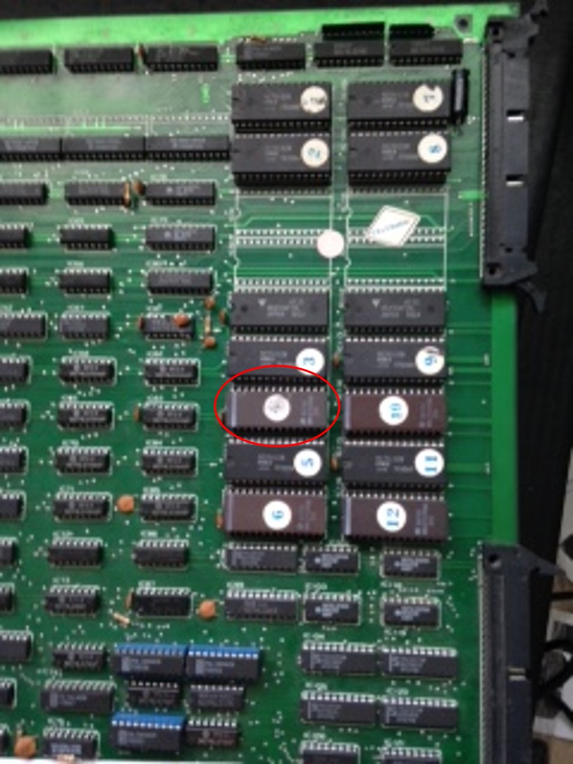
The number on the resistor that you called a 103 is: KL09S103JTB. I don't suppose you know where I can get one. I searched for that number of google and came up blank.
The chip that I put on backwards is in the photo below. I suppose I will know if it is working ok when I plug the board back in because it seemed to affect the top half of the screen when I got it wrong, so I would expect the picture to come back if it is still ok.
Regarding the chip with the resistor on it. That is the chip that has a missing leg. I think I might be able to solder a wire in to make the connection again running from the stub of the missing leg down to the board...
Thanks
yes that chip is a eprom and is 99.9% likely to have blown if put in the wrong way round, if your lucky you sometimes see a little bright white flash from under the quartz window on the top of the chip, but yes it will be destroyed.
8 resistors in a 9 pin package, SIL 10k
http://www.ebay.co.uk/itm/331702127946?_trksid=p2055119.m1438.l2649&var=540818922001&ssPageName=STRK%3AMEBIDX%3AIT
ok QTY20 is excessive, but thats what your looking for
8 resistors in a 9 pin package, SIL 10k
http://www.ebay.co.uk/itm/331702127946?_trksid=p2055119.m1438.l2649&var=540818922001&ssPageName=STRK%3AMEBIDX%3AIT
ok QTY20 is excessive, but thats what your looking for