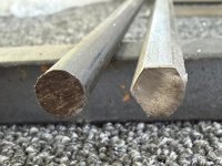
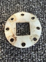
Well you know the old saying, when the wife's away . . .
With her indoors gone for the day, it gave me time to get started on the bearing housings. First order of the day was to get the mill trammed back into square. After all the work making the bearing jig and other projects, I needed to ensure the mill head was still true to square to the bed. This involves loosening some nuts and rigging up a dial indicator. You first get the side to side reading done by placing the dial indicator to the left and setting the dial at zero, then swinging round 180° and check if it's still at zero. If not, the divide the difference by 2 and tap on the mill head assembly with a rubber mallet to align. Happy when both read zero. Then onto the front to back. Once all aligned again, time to get started.
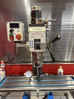

This will require yet another jig. We need to control the centring of all the drill bits and end mills to do the main bearing holes, especially as these are curved to hold the bearing, but we also need to drill the holes needed for the bolts to pass through. There are three of these set at 120° apart on centre.
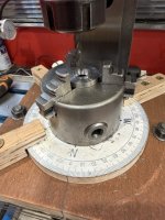
Cut out a piece of 1/2", 18mm, ply to sit across the mill bed, and added two strips that fit into the two outer t-slots. the centre slots were than able to slid along and clamp into the board, you can see this in the third photo below. On top of the base board I added a 1/4", 9mm, board, rounded and with a compass stuck onto it. This was marked out at the required 120°, which aligned with a marking on the bas board. Had to add a couple of hold down clamps to stop it from rotating with the drill bit. A three jaw chuck was then added to that in which to securely hold the bearing housing halves. Everything was aligned centrally and clamped down.
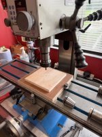
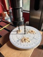
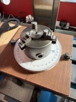
Now onto the parts. We need to mark the centres of both halves to ensure the drill holes are aligned centrally. Drill bits tend to wonder and flex slightly, allowing it to start drilling off centre, which can allow snap your bits, oh err. Once all was marked up, time to start drilling the holes. Start small and move up to till the largest size needed. This reduced any strain on the mill, though does mean a lot of switching bits in and out, and cleaning up after each part is done.
Finally when all the parts are sized out, we move onto the big ballnose bit. This is just slightly larger than the diameter of the bearing, so it can move freely within the bearing housing. The depths were set and off I went. Taking it easy and at low speeds so as not to tax the mill too much. Once each part was done, hovered the metal fragments, turned the part over, and made a slight relief on the opposite side.
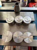

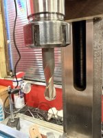
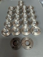
Finally, once finished and after a good clean, it was time to see if the rotation actually worked. Using an original as a guide, I move the mill bed into place, switched out the ballnose bit for a 4mm jobber drill bit, and drilled the first hole. Nice, then the other two, rotating 120° after each. First test fitting, this against an original part. They both matched up brilliantly, so ever onward and upward. You can see the two original halves at the bottom of the last photo.
The first half is now finished, bar some final cleaning and smoothing. I'll get these blackened so to protect them and stop them from rusting. Might be nice to do these in stainless steel as well, though it would mean upgrading the ballnose bit to a carbide version, over $150 a bit, so will see.
Next up will be to drill and tap the other side of the bearing half, and that'll be the joystick and bearing assembly finished.
This will now bring me onto the lower part of the joystick frame. The part that the leaf switch attach onto. Need a wee think about this part.