shinobi bootleg some colours wrong.

Lurch666

Active member
Feedback
21 (100%)
Credits
4,090CR
I'm working on a shinobi boot that's a copy of the system 16A board.

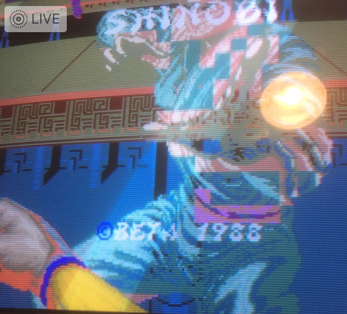
The actual gameplay screen looks fine but the title,mission and bonus screens are not correct.

2019-12-28_12.36.36.jpg


I think I have traced the fault to pin11 of IC78 stuck low.

It's fed from a PK8701 (IC81) that seems to be a pal type copy of a sega custom so I think maybe I'm stuck.

I have tried replacing a 74LS27 that it connects to and am thinking of replacing the 74LS153 as well just in case it is holding the line low but I doubt it's going to make a difference but it's all I can do since I can't find anywhere that has the code for replicating the custom.

Does anyone else have a bootleg shinobi that looks like a system 16A?

I was wondering if you could check to see if there is supposed to be a signal on pin 11 of IC78 just to make sure I'm not chasing a dead end.

it's annoying since the game itself is fine but I just can't leave this nearly working.
 

Lurch666

Active member
Feedback
21 (100%)
Credits
4,090CR
bones said:
Don't know the board but I had some ls 175s messing the colours up on an altered beast.

Were the colours messed up on all the screens or just certain ones?

This what puzzles me about his one since the colours are fine in gameplay screens but wrong on the title,mission and bonus screens.
 

Lurch666

Active member
Feedback
21 (100%)
Credits
4,090CR
@Retroman839:Yep that's the same as my board except that the daughter board on the bottom is bigger on yours.

You seem to have similar colour problems as me but yours are worse.

The ninja that jumps at you when you fail the bonus screen is fine on my board but when testing I found that it's probably the same array of 6 315-2015 (IC73-IC75 and IC80-IC82) that handle all the graphics.

If you have a scope or probe you could do what I did and check the data coming out of those.

Some pins are inactive during certain parts of the demo because I found that pins that were inactive during the gameplay demo were active during the title screen or bonus screen but only pin 15 of IC 81 that fed pin 11 of IC78 stayed low all the time.

Thanks to the info here I have now realised that all these customs are the same copies of the sega 315-5025 chips and not pals with different configurations in them like I first thought.

I'm thinking of removing ICs 80 and 81 and swapping them to see if the colour problem changes to confirm that it's IC 81 that has failed.

The other thing is the replacement 315-5025 that Caius makes only has 18 pins but on this board the same chips are 20 pin.Are they still compatible?
 

Retroman839

Senior Member
vacBacker
Feedback
12 (100%)
Credits
7,043CR
Hey man good work!

When I’m back
I’m getting scope & probe out..

Sounds like you have found the inactive
Source..

I’m only at reading stage with logic at mo
But I’m trying to learn
smiley5.gif


Does your game say beta in bottom corner @ title screen?

Like I was getting a lot of text absent at the score table also
And the little icons lightning whirlwind etc...
missing....

Im pissing in the wind but we are both having similar result
With the board so could it be that this is how the bootleg is?
Might be worth a mame boot version rom test?Retroman8392019-12-29 11:29:19
 

Lurch666

Active member
Feedback
21 (100%)
Credits
4,090CR
I have just finished swapping ICs 80 and 81 around and I have a good result.

Checking with my scope I now have a signal on pin 15 of IC81 but obviously I am now missing the signal on pin 15 of IC80 so I do need a 20 pin replacement 315-5025.

The title screen looks a bit better now with more black but it's still not correct because of the now faulty chip at IC80.

@Retroman839-When I've got a bit more time I'll make a list of pins for you to check with a photo showing where the chips are on your board.

Dunno about swapping boards around between genuine and bootleg system 16 boards but one thing I did find out was that my board is missing some connections from the schematic like pin 11 of the 315-5025 that are tied to 6M on the schematic were just tied to ground on my board.
 

Retroman839

Senior Member
vacBacker
Feedback
12 (100%)
Credits
7,043CR
nice one
Nah I don’t mean putting genuine daughter board
On a boot man board...

I mean like swapping a golden axe bootleg daughter board
With one of these shinobi boot leg

Boot leg to boot leg hot swapping
smiley20.gif
Retroman8392019-12-29 12:00:56
 

Lurch666

Active member
Feedback
21 (100%)
Credits
4,090CR
As far as I know the daughter boards are just for replacing the sega custom chips.

I did swap a daughterboard from a bootleg wonderboy in monsterland with one from a bootleg choplifter since those two daughter boards were identical.
 

Lurch666

Active member
Feedback
21 (100%)
Credits
4,090CR
shinobi_pcb.jpg


OK here's what I did to test mine.

There are a set of six 74LS153 numbered 64,65,71,72,78 and 79.

On the schematic they are the large block in the middle of page 4 and the inputs are merked 16A,15A14A16B,15B and 14B and it also shows which IC is which (16A is IC78 for example).

Now these are fed from the chips in page 3 so I tested all the pins on the 153 to see if there was a signal present.

The pins you need to check are

16A pins 3,4,5,11,12,13

15A pins 3,4,5,11,12,13

14A pins 3,4,5,11,12,13

16B pins 4,5,11,12

15B pins 4,5,11,12

Now remember that some of these pins are ONLY active during one part of the demo sequence (title,gameplay,bonus screen or highscores) so you need to keep checking while the whole demo sequence plays out.

If you find a pin that is inactive then you can use the schematic to trace back and see which chip it's connected to and see if that chip has active inputs and so on till you find a possibly faulty chip.

On mine I found pin 11 of 16A was constantly stuck low (which is SB1 on the schematic I think) which comes from IC81 although the schematic says pin 13 continuity showed it to be pin 15 because the 315-5025 chips on this board are 20 pin instead of 18 pin so they are out.

I then checked the inputs (pins 1-8) on IC81 and found them all active which led me to believe that IC81 was at fault.
 

Retroman839

Senior Member
vacBacker
Feedback
12 (100%)
Credits
7,043CR
wow i follow you

yeh ok so the pin numbers are shifted
because it’s a 20pin and not an 18..

right if i find a stuck low more than likely faulty...
i read sometimes a stuck low can be pulsed out
or slightly increased voltage for example if 5v
5.1 can give sound on a boot where 5v did not...
stuck low can sometimes be a result of low voltage?
 

Lurch666

Active member
Feedback
21 (100%)
Credits
4,090CR
A stuck output can be either high or low and varying the voltage can make a difference but with this board it was actually a faulty chip.

Quite a few boards I own are very voltage sensitive and require adjusting till all the graphics appear properly but no amount of adjustment could sort this shinobi out.

The 315-5025 was for some reason was a 20 pin device on some boards and 18 on others but talking to Caius it seems that the extra pins (pins 10 and 11) are just tied to ground anyway so the 18 pin version can be used to replace the 20 pin version.

I've got a replacment coming from him now so will post back when I get it.
 
Top