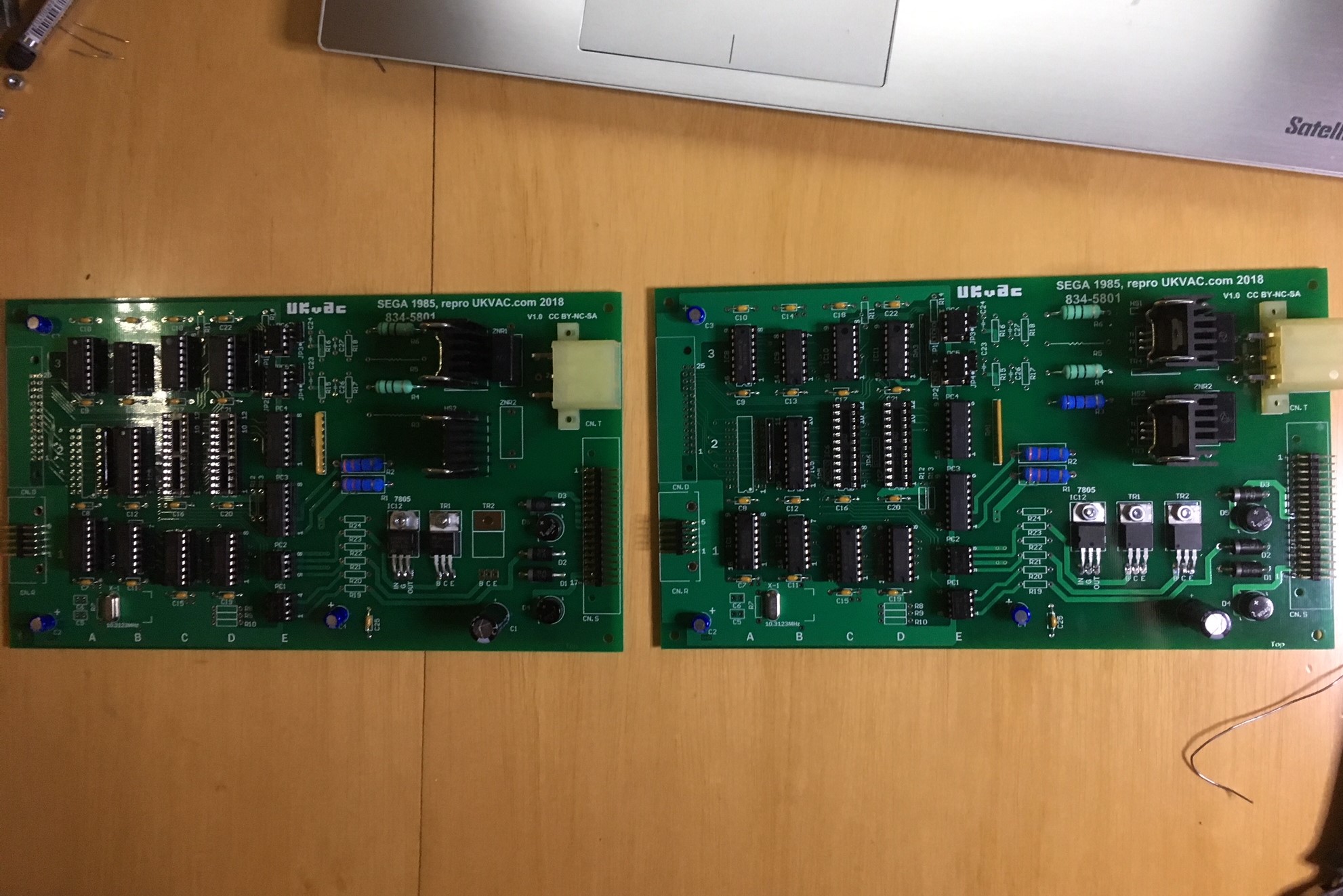
Space Harrier /OutRun DX Motor OpenBoard Project

John Bennett

Senior Member
vacBacker
Feedback
10 (100%)
Credits
4,991CR
karlcdoe said:
John Bennett said:
I’m travelling at the moment, but things are still in motion (in addition to James’s creaky cab).

Apologies if I’ve overlooked a previous offer, but would anyone be able to try a board in a Space Harrier and give feedback (within the next week)? The 2 things untested are dual-motors and 60Hz, so would be good to at least try dual motors ASAP. As with other protos, the option would be there to buy it (about £50) to replenish the costs. There’s negligible changes from proto to the next version and it’s ‘limited edition’
smiley36.gif

I never bothered screwing down the access panel (or the pcb!) on my cab after I fixed my original motor drive  pcb so if nobody else wants to throw their hat in the ring I'll give it a whirl if you like.

Cheers

Karl.
That’s great Karl - thanks. I’ll PM you once it’s built (over the weekend hopefully).
 

Jodo

Boy is this a machine!
Staff member
vacBacker
Feedback
15 (100%)
Credits
607CR
I don’t currently have power to my Harriers which is why I haven’t volunteered for testing. That should be sorted imminently but I didn’t want to delay progress when there are other members with working machines accessible:)
 

tin

Active member
vacBacker
Feedback
3 (100%)
Credits
649CR
Jodo said:
I don’t currently have power to my Harriers which is why I haven’t volunteered for testing. That should be sorted imminently but I didn’t want to delay progress when there are other members with working machines accessible:)

Harriers?
smiley3.gif
 

John Bennett

Senior Member
vacBacker
Feedback
10 (100%)
Credits
4,991CR
Thanks everyone for the support
smiley1.gif


I'm trying to get as much done in parallel, so these final two prototypes are more of a reassurance than something we'll delay things over (although I will try to hang on with the V1.1 PCBs until I know it's 100%). It does seem unlikely there's anything wrong with it now, but you never know.

Got a mini production line going now. Shame I stuffed up my last Farnell order, so a few bits short. It takes a little over an hour to solder one up, so not quite a 5 minute job.

IMG_2403a.jpg


Pre-orders thread will come soon-ish. A bit anxious that a few devices are going out-of-production now - e.g. 74LS240's (they weren't back in May).
 

John Bennett

Senior Member
vacBacker
Feedback
10 (100%)
Credits
4,991CR
Ok, I've stuck up a pre-orders thread. I hope it's worded OK

pre-orders

Apologies if you've already expressed an interest, but could you register it on there too.

We need the pre-orders now to gauge the final costings and consider the logistics of testing and shipping.

I should say - 'thank you' for the kind offers of donations. Howver, it's my hope that if we can make a small profit, that will more than cover the development costs so-far, although I am hoping we can sell the 3 prototypes too (to recover the cost of parts).
Our profit will depend on how many parts we can order at once from Farnell (which will also depend if we order for the whole world and make the units in the UK).
 

iamjimmi

Active member
vacBacker
Feedback
8 (100%)
Credits
481CR
Apologies...this is a little off topic...

Wind the clock back to how this project started and you may remember that I secured a DLX SH that was missing all PCBs.

With the result from this fantastic project, I now have the movement control board, and in the meantime I have managed to secure the game boards and correct sound amp.

The last missing piece of the puzzle is the lamp drive board 834-5809.

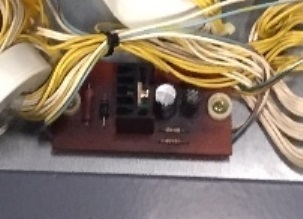
The board makes the lights in the seat headrest flash and looks like to be quite a simple bit of kit. Best photo I could find is here:

834.5809.jpg


I couldn't find any schematics.

Would anyone be prepared to help me create one of these? I will of course pay for your time and materials. Even though it looks quite simple - to someone with my lack of skills it is still beyond what I could attempt!

If anyone is up for a mini project to help me complete the board set, please PM!

Thanks in advance....

 

John Bennett

Senior Member
vacBacker
Feedback
10 (100%)
Credits
4,991CR
It’s probably just a power transistor circuit - same sort of thing used to drive the clutch (brake) on the drive boards. I’ll take a look at what’s on the wiring harness schematics.

So have you got game boards too?
smiley16.gif
 

iamjimmi

Active member
vacBacker
Feedback
8 (100%)
Credits
481CR
John Bennett said:
It’s probably just a power transistor circuit - same sort of thing used to drive the clutch (brake) on the drive boards. I’ll take a look at what’s on the wiring harness schematics.

So have you got game boards too?
smiley16.gif

Thanks John... appreciate any help you can provide.

Yep, I now have a working game boardset! I still need to refabricate the missing metal panels but life has got in the way so I haven't had time to progress this yet....
 

smarty

Ready Player One
vacBacker
Feedback
12 (100%)
Credits
1,290CR
iamjimmi said:
Yep, I now have a working game boardset! I still need to refabricate the missing metal panels but life has got in the way so I haven't had time to progress this yet....

Sorry to go off thread topic...I think I still have a metal backing plate for an Enduro/Harrier upright PCB set it holds all the game PCBs . Is it the same in a DLX and is it what you’re after? Yours for free, but arkward to post, i’m Sure we can come up with something if it can be of use.smarty2018-11-08 09:33:47
 

John Bennett

Senior Member
vacBacker
Feedback
10 (100%)
Credits
4,991CR
No worries about being ‘off topic’ - I’m hoping the development is finished on the motor drive anyway ??

I expect it would be useful to many to know what’s on this lamp PCB.
 

karlcdoe

Active member
vacBacker
Feedback
7 (100%)
Credits
864CR
smarty said:
iamjimmi said:
Yep, I now have a working game boardset! I still need to refabricate the missing metal panels but life has got in the way so I haven't had time to progress this yet....

Sorry to go off thread topic...I think I still have a metal backing plate for an Enduro/Harrier upright PCB set it holds all the game PCBs . Is it the same in a DLX and is it what you’re after? Yours for free, but arkward to post, i’m Sure we can come up with something if it can be of use.

There's no metal backing plate on my DX pcbs, they are just screwed to some wood in the base of cab. I had a few mini uprights in the past so I think I know what you are talking about and perhaps they decided they didn't need it on a metal cabinet if its for emi requirements.
 

Mr20to5

Active member
vacBacker
Feedback
1 (100%)
Credits
1,360CR
I may be wrong but I think Jim is referring to the missing metal panels that cover the entire base assembly.

He needs to get these fabricated, then send everyrhing off for powder coating, then start the reassembly.

(Maybe)
 

iamjimmi

Active member
vacBacker
Feedback
8 (100%)
Credits
481CR
neil1637 said:
I may be wrong but I think Jim is referring to the missing metal panels that cover the entire base assembly.

He needs to get these fabricated, then send everyrhing off for powder coating, then start the reassembly.

(Maybe)

Thanks Neil... you are correct!

But Martin, I would love the metal backing plate for the PCBs. I am in no rush for it, so if you don't mind holding onto it, maybe I could pick it up at a meet or event next year. Or maybe when the Jedi is delivered (still way off completion!)... ??
 

karlcdoe

Active member
vacBacker
Feedback
7 (100%)
Credits
864CR
[lamp flasher minor thread hijack follows]

iamjimmi said:
Apologies...this is a little off topic...

The board makes the lights in the seat headrest flash and looks like to be quite a simple bit of kit. Best photo I could find is here:

There should be almost enough info in the following pictures should anyone wish to build one, looks practically hand made anyway....

SH_lampDriver_1.JPG


SH_lampDriver_2.JPG


SH_lampDriver_3.JPG


SH_lampDriver_4.JPG
 

John Bennett

Senior Member
vacBacker
Feedback
10 (100%)
Credits
4,991CR
Thanks again Karl
smiley16.gif


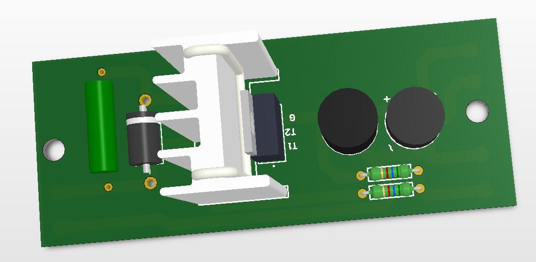
Even simpler than I expected.
Low-voltage AC goes in, gets rectified and smoothed to DC.
Signal from game goes in, switches low-voltage DC onto the lightbulb via the PNP transistor. Diode is there to take out any spikes.

The resistor? Without too much thought, I'm assuming it goes between dim and bright, rather than fully ON and OFF?

Might as well knock up a PCB design as it's quick enough to do and we should record the schematics anyway, but would anyone else on the planet need one?
smiley36.gif
.

(would work on stripboard too, obviously, just looks a bit sh*t)
 

John Bennett

Senior Member
vacBacker
Feedback
10 (100%)
Credits
4,991CR
Any chance someone could get some dimensions, please?
Would be nice to get the board 1:1, but the space between the two drill holes is the key detail.

Jim - you might be able to see the two holes in the cabinet to work it out.
 

iamjimmi

Active member
vacBacker
Feedback
8 (100%)
Credits
481CR
Wow... that looks incredible!

The PCBs all sit on a wooden board that can be removed to work on the boards. And my wooden board is missing... so I can't help with the dimensions I'm afraid...

Anyone else?
 

tin

Active member
vacBacker
Feedback
3 (100%)
Credits
649CR
If it’s the same board as outrun DLX I can get of course. But it’d be a few days, so someone must be able to beat me to it.
 
Top