Space Harrier /OutRun DX Motor OpenBoard Project

John Bennett

Senior Member
vacBacker
Feedback
10 (100%)
Credits
5,003CR
Yes, it turns the mains to DC, then fires a transistor bridge to power the motor, so there’s none of the clever mains-sync stuff needed. Even more in my ‘comfort zone’ for a circuit (made many similar circuits in my time).
But is there a need to make up PCBs? If there was, we could rope in our French counterparts
smiley16.gif
 

NaokiS

Active member
Feedback
1 (100%)
Credits
116CR
I'm looking at doing a personal replication of the dsb1 and driver io boards from my STCC driver cab just to supply schems tp the world and ideas to the group, also because aside from the DSB1s sega custom (rebadge cpld most likely) its all generic parts!
 

John Bennett

Senior Member
vacBacker
Feedback
10 (100%)
Credits
5,003CR
Minor update - been routed for a little while and passes all the checks.
So just 'touching up' now (get in with any last minute routing tweaks if you wish
smiley36.gif
).

I'll order the bits for a unit this week, see if they match a printout of the schematics, then get some PCBs ordered after that.
I think it's going to be roughly in the order of £50 in bits, plus the PCB, but I'll do the finances properly soon (and set up a money reserve
smiley1.gif
).
There's no particularly expensive components, just lots of them. I'll socket everything too which adds a couple of quid, but peace of mind.

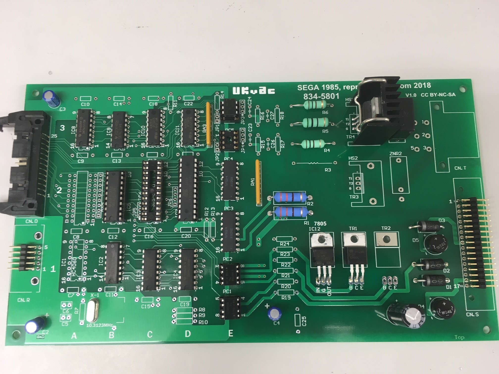
Latest draft if anyone wants to cast an eye over.

834-5801_20_6_18.Zip
Having stared at the schematics and GAL enough, I think I get how it all works now (I'll write a manual detailing it).
Also, finally settled on a heatsink. It's intended for the TO247, but should fit the TO220 (the correct TO220 heatsink looked a bit small compared to the original).

noparts.JPG

pcb_20_6_18.JPG
 

PhilT

Active member
vacBacker
Credits
154CR
Great project, just wish I understood what wizardry was happening here but alas.
More than happy to chip into the project prototype fund though and would definitively want to buy one for my Outrun cab.
 

John Bennett

Senior Member
vacBacker
Feedback
10 (100%)
Credits
5,003CR
I’ve not found a single incorrect tracking error in the routing ! It was more you finding errors in the schematic via the routing!
smiley36.gif


Thanks Phil, Clarkey! We’ll take pre-orders and start the ‘advertising’ once I’ve tested a unit, so hopefully not too long.(but I’ll take note
smiley16.gif
)John Bennett2018-06-20 23:31:16
 

ben76

Hunts Spies
Feedback
7 (100%)
Credits
1,136CR
I'd change it to say ukvac.com instead of just ukvac then people can find the amazing work you've all done easier :)
Great work done by all involved :)

-Ben
 

NaokiS

Active member
Feedback
1 (100%)
Credits
116CR
That's actually a smart idea to be fair, plus if someone buys it second hand or is troubleshooting it, easy to find where to ask questions!
 

John Bennett

Senior Member
vacBacker
Feedback
10 (100%)
Credits
5,003CR
Yes - I changed it to that yesterday as it made a lot of sense.
Sent off for the bits from Farnell tonight, so wheels still in motion
smiley16.gif


Edit: the hope it to create a very detailed manual, like wot you got with stuff like defender, where it describes each part of the circuit and gives the criteria for suitable alternative parts (should the bit we’ve used become hard to source).John Bennett2018-06-22 23:50:23
 

John Bennett

Senior Member
vacBacker
Feedback
10 (100%)
Credits
5,003CR
Minor update:
Purchased parts for one PCB (except for the white motor connector).
Checked for fitment, hole-size etc.
Few minor tweaks.
5 PCBs ordered from ALLPCB for £30 (Thanks Colin!)

So if you see anything wrong with the PCB presently on CircuitMaker (not the pdfs in this thread), let me know as I'll have to wire-mod these. (just posting this incase anyone is tempted to tinker with it).

So it might go quiet again for a little while.
smiley1.gif
 

Jodo

Boy is this a machine!
Staff member
vacBacker
Feedback
15 (100%)
Credits
607CR
Fantastic news :)

How do you plan to generate the signals to the proto PCB to test that it (in turn) sends out the correct movement instructions (I’ve explained that badly but you get the idea I hope)....
 

John Bennett

Senior Member
vacBacker
Feedback
10 (100%)
Credits
5,003CR
I was going to be lazy and just start with a 4-bit dip switch. But I see you can get 16-way rotary binary dials for very little money, so I might go for that (I wouldn’t inflict a dip switch on Naoki if he’s going to be testing loads of these
smiley36.gif
)
 

John Bennett

Senior Member
vacBacker
Feedback
10 (100%)
Credits
5,003CR
When I get the first unit done, I'll make a test document and have a think about 'mass production' and what to check.

I/O wise it's pretty simple (hence switches and LEDs were my plan), but it's knowing the high-voltage motor drive part is behaving 100% on every unit that's trickier . I was thinking about a combination of lightbulb (to give it some current) and oscilloscope (to check triac firing and 'motor' direction). Would be nice to avoid posting heavy transformers and motors (which you can't load up on a bench anyway).

edit: It should cope with 110V though, so at least they're easy to get ahold of.John Bennett2018-06-29 17:10:57
 

NaokiS

Active member
Feedback
1 (100%)
Credits
116CR
Mmm that looks minty fresh. And possibly the first board I routed without me making a huge oversight! Lol

Ill see about making a 3D mockup of the connector housings so we use them with standard header pins, though may need to add mounting holes for suchNaokiS2018-07-06 13:33:27
 

John Bennett

Senior Member
vacBacker
Feedback
10 (100%)
Credits
5,003CR
It’s feeling like 50% electronics, 50% art project
smiley36.gif


There are holes by those connectors and they’re just eyeballed from the photos, so we can alter them if it helps with making surrounds (although it’d be nice to verify the holes suit the original connectors too).John Bennett2018-07-06 14:04:27
 
Top