Space Harrier /OutRun DX Motor OpenBoard Project

John Bennett

Senior Member
vacBacker
Feedback
10 (100%)
Credits
4,997CR
Thanks everyone.
What I'll do for the connectors is:
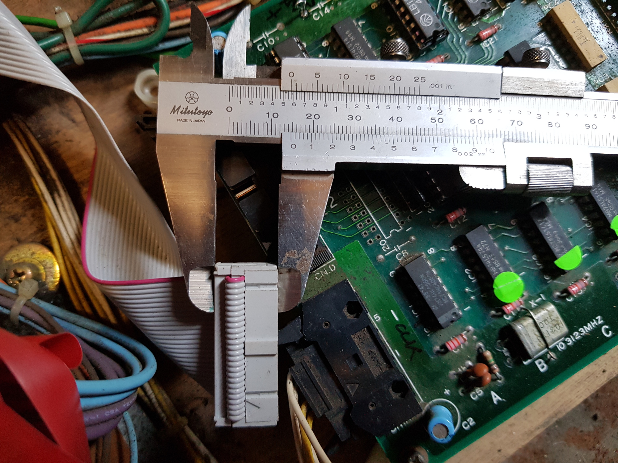
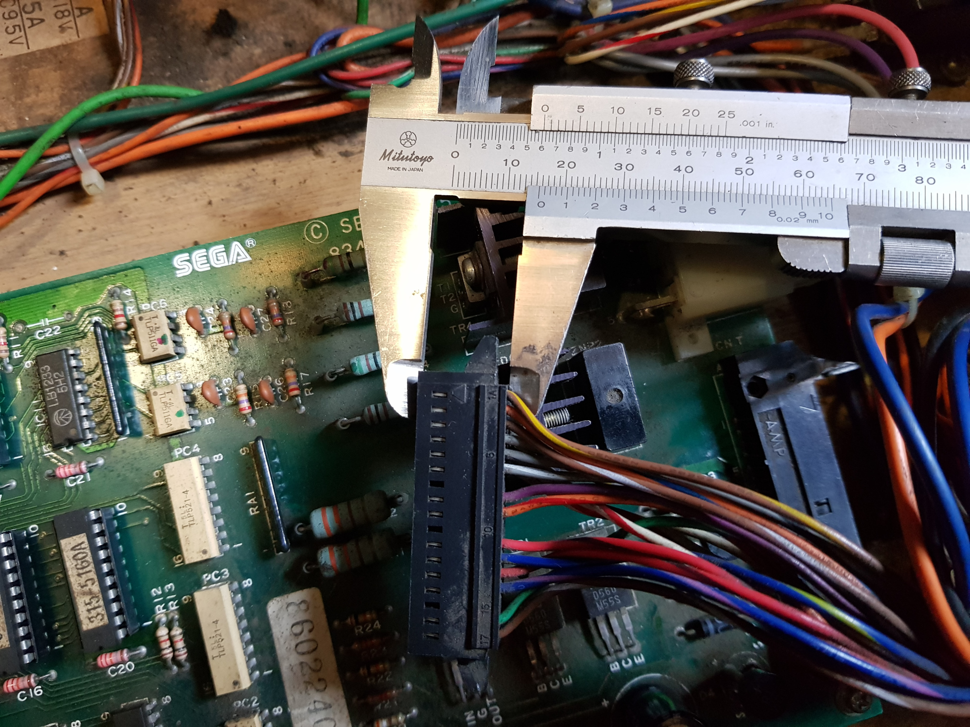
CN.D (control cable) - IDC socket with long-reach latches so it'll go around a cable with the restraining strap (not on Karl's replacement, but on Outrun2's photo). This is as in the PCB graphic a few posts back
smiley1.gif


CN.A and CN.S - as these are obsolete, you can transplant your old header, but I'll source some bare-pin, right angle 2.5mm headers.

http://www.goodluckbuy.com/images/detailed_images/sku_83926_2.jpg

CN*T, we can get, amazingly.
 

NaokiS

Active member
Feedback
1 (100%)
Credits
116CR
All sounds good. It might be possible to even have a 3D printed box made for standard RA headers. I can see about replicating the connector that is on my Touring Cars cab which looks identical to the Outrun/SH ones.
 

NaokiS

Active member
Feedback
1 (100%)
Credits
116CR
karlcdoe said:
Bit late now perhaps but here are the two control connectors:

cpu -> drive pcb: (note this is not the original cable, I replaced it for the hell of it during repair as for some reason being a resourceful fellow I had a few new ones in a box, some ribbon cable and the tool used in a vice to clamp them...)

SH_CPU_CN.jpg


drive pcb <-> clutch/24v power/etc:

SH_Clutch_PWR_CN.jpg


The +5vdc power supply from the switch mode is using 'standard' sega locking connectors, not sure what they are but think someonw struglged to source identical usnits but found something usable but not locking and put it in the connector kits that were for sale for power drift/outrun, etc here.

Thr connector he's selling is a double row dupont connector, same style as used in many pcs
 

John Bennett

Senior Member
vacBacker
Feedback
10 (100%)
Credits
4,997CR
Haha, might as well throw CAD and 3D printing into this as well
smiley36.gif


Sorry, missed the bit about the connector kits - does it basically get us a plastic surround for the pins (but no locking)?
 

NaokiS

Active member
Feedback
1 (100%)
Credits
116CR
John Bennett said:
Haha, might as well throw CAD and 3D printing into this as well
smiley36.gif


Sorry, missed the bit about the connector kits - does it basically get us a plastic surround for the pins (but no locking)?

No, for original cab owners, they'd have to use either original recepticals or the Right Angle header pins. For custom harnesses, they can use any .1 inch connector they want such as standard header pins, IDC, even JST RA.
 

John Bennett

Senior Member
vacBacker
Feedback
10 (100%)
Credits
4,997CR
A couple of help requests, please
smiley1.gif


I've attached a .pdf of the schematics and PCB as-is (so nearly done).

834-5801.Zip

Would anyone with a board be able to take a glance and see if we've done anything obviously wrong with the headers (or anything else).
I'm still messing with the settings for the pdf, but hopefully you can gauge the placement of the pins and the holes.
The hope is that the pads and mounting holes match the original parts (so you could transplant them all if desired).
I'm feeling some of the pads are a bit on the small size. It should print 1:1 scale. Oh and there’s a few tracks around the triacs still to route (so don’t worry about that).

Second question - we need right-angle pin headers in place of the Amp connectors. The difficulty is that they have to be raised-height to standard headers as the IDC/Amp headers have the pins a bit higher off the board. Any recommendations?

This is a typical header:
DIL-Header-Right-2.png

We need the pins on the side without the plastic to be longer, so it can stand a bit higher off the PCB.

Nearly done the bill-of-materials. The Darlington transistors for the clutch (2Sd560) were maybe the trickiest as they're obsolete and there's nothing close enough for my liking (whilst pin-for-pin compatible). I'm just going to order a logic-level MOSFET (FQP13N10L)and try that - hopefully way better and cheaper...

John Bennett2018-06-12 23:46:27
 

NaokiS

Active member
Feedback
1 (100%)
Credits
116CR
For the right angles, there should be no issue using standard stuff. The hight is fine and if a little off, it only needs to have the plug connected during soldering asa shim. verified with my driving cab amps
 

iamjimmi

Active member
vacBacker
Feedback
8 (100%)
Credits
481CR
John, would it help if you have an original board at this stage of the project?

I wouldn't like to post my board - it belongs to Andreas and I just wouldn't want to risk it getting lost in the post - esp after all of it's history.

But I could drive up to Newcastle with it next week if that's what it takes...

iamjimmi2018-06-13 21:33:54
 

tin

Active member
vacBacker
Feedback
3 (100%)
Credits
651CR
The one I've been using is available if you want. It's from an outrun (so one set of the components is missing) but as we know it's basically the same. It has a couple of components missing so I presume in the past it's been pillaged for a part or two.

However I'll also get specs/dims/whatever needed from it if that will suffice. I've been a little off the radar for a couple of weeks, but should be able to devote 1/2 hour a night or so.
 

John Bennett

Senior Member
vacBacker
Feedback
10 (100%)
Credits
4,997CR
I didn't want to ask for a board as I appreciate they're rare (hence this thread) and I figured we could get something working without one, although it makes for a more accurate bootleg having one to look at.

So thanks for the very kind offer Jim
smiley20.gif
, but I was thinking that hopefully James (tnanks again) and anyone else with a moment can get us close enough by comparing a printout to the real board. We can then then refine it after the first PCB.

I've been thinking that the best plan-of-attack is:

Order components for 1 PCB.
Check components on printout for obvious mistakes.
Finish PCB
Order 1 PCB of V1.0*
Assemble and test one PCB using simulated environment (80V via transformer, DIP switch inputs, DC motor etc).
JB either travels with, or sends, a PCB so someone to try on a real game.
Refine the PCB if needed (V1.1)
Take a load of pre-orders.
Order a batch of PCBs.
Order parts for those who want assembled boards
Assemble and test boards for those who require (we'd have to agree on a price, although it'd be reasonable)**
Post stuff.
Think about V1.2 if people complain
smiley36.gif


*I'm tempted to fork out £90 to get a one-off initial PCB done properly as the time required for me to drill and hand-via a copper-only 'homemade' PCB isn't worth it, having now seen the near-finished item. Plus it'd be nice to see the silkscreen.

** I'm not making them - I'd lose the will to live after a couple
smiley36.gif
I think Naoki was contemplating it. I'll send on the testbench used on the intial PCB to whoever is doing it.John Bennett2018-06-13 22:15:39
 

tin

Active member
vacBacker
Feedback
3 (100%)
Credits
651CR
John Bennett said:
A couple of help requests, please
smiley1.gif


Would anyone with a board be able to take a glance and see if we've done anything obviously wrong with the headers (or anything else).
I'm still messing with the settings for the pdf, but hopefully you can gauge the placement of the pins and the holes.
The hope is that the pads and mounting holes match the original parts (so you could transplant them all if desired).

I'm feeling some of the pads are a bit on the small size. It should print 1:1 scale. Oh and there’s a few tracks around the triacs still to route (so don’t worry about that)

regarding the connectors CN C and CN R are slightly off position but the pitch etc looks right and I think that doesn't provide any cause for concern.

The only thing I spotted so far is not all the GNDs on CN R are connected to the main gnd rail on the board. it looks like only 4B is connected. should be 4&5 A&B.

I will do a lot more checking tho.

Does it get markedly cheaper to order several boards? i.e. is there a large setup cost that could be shared? I'm interested to have one too. I'll mod the board around mistakes if there are any.
 

John Bennett

Senior Member
vacBacker
Feedback
10 (100%)
Credits
4,997CR
Yes, costs go down hugely as numbers go up, fortunately. A batch of 50 worked out something close to a tenner per board.
We could do a few protos, for sure, if you don’t mind the odd mod.
smiley1.gif


The parts look pretty cheap too. Nothing standout expensive on there (which was the intention)

Great if you’ve already spotted the odd issue. Would be nice to get the protos spot-on.John Bennett2018-06-13 23:26:55
 

John Bennett

Senior Member
vacBacker
Feedback
10 (100%)
Credits
4,997CR
In hindsight, I probably should've spent a little time on the schematic before printing it, as I've spotted a few screw-ups already. IC8 doesn't have a clock (I forgot to put it on the part), so that explains why there's a track to pin 9.
I did run a design rule check and it's pretty good - the above was the only 'short circuit' that's present (as we'd put a track to the pad).

I'm playing with the PAL equations at the moment, which is helping understand things (might rename a few nets/tracks too for easier understanding).
 

Nes4life

Active member
vacBacker
Feedback
11 (100%)
Credits
1,117CR
Can’t wait to see the proto! I don’t have any games that use this but I’m in awe of the effort gone into it.
I love the process and the investigatory work. Hopefully you’ll get a good number of preorders to get the price down.
 

NaokiS

Active member
Feedback
1 (100%)
Credits
116CR
Hey, just was browsing through system 16 and looks like that rad mobile uses a similar cabinet movement system like Outrun, wonder if it and maybe more use either this board or similar?

Oh and I wasn't contemplating assembly work, I was stating I'd do it
smiley36.gif
NaokiS2018-06-14 10:15:05
 

tin

Active member
vacBacker
Feedback
3 (100%)
Credits
651CR
Re-jigged the schematic relating to pin 2 on our favourite CN.T and made a couple of polys including the bloody big RET one. Could you check my work? it's the first time I've tried this lark in CM and it seems right but I could have made a balls of it.

If they're good (or pretty good) I'll do the rest.

Regarding Radmobile I'm sure it's a completely different board, albeit on the same principles. I'll take a closer look at the board in the coming days.

tin2018-06-14 10:56:05
 

karlcdoe

Active member
vacBacker
Feedback
7 (100%)
Credits
875CR
I will take a look at my orig board and compare to the proto if I can find a moment as you guys did all the work drawing the traces, etc. I may/may not spot anything useful before my eyes go wonky and to be upfront I'll declare myself in the 'not prepared to ship orig pcb' camp for the minute.

however, working on the assumption that at least one initial pcb will need to be ordered before the last errors are spotted, rather than one big batch order followed by a lot of wire wrap I'm happy to throw in a non conditional £30 into the pot if you are considering getting one made up, I assume payPal gift is easiest?

karlcdoe2018-06-14 11:33:54
 

John Bennett

Senior Member
vacBacker
Feedback
10 (100%)
Credits
4,997CR
Thanks Nes4Life. I've not got a machine that needs one either - might just stick a board in my wife's display cabinet alongside the ornaments.

Naoki - I didn't want to commit you to it incase you'd had second thoughts LOL]

tin/James - busy morning! I hadn't spotted the error on CN*T. I never use polygons in this way, but it looks good and seems like you've done it ok, although I think you might have to change the thermal-relief settings for some of the polygons as they need to touch the pads all around as they're for carrying high current (this is just the power tracks in the high voltage section ). The other option is to draw thick tracks from the pads into the polygons, which might be useful in some cases (there's a hotkey somewhere to change track widths as you route them).
 

John Bennett

Senior Member
vacBacker
Feedback
10 (100%)
Credits
4,997CR
karlcdoe said:
I will take a look at my orig board and compare to the proto if I can find a moment as you guys did all the work drawing the traces, etc. I may/may not spot anything useful before my eyes go wonky and to be upfront  I'll declare myself in the 'not prepared to ship orig pcb' camp for the minute.

however, working on the assumption that at least one initial pcb will need to be ordered before the last errors are spotted, rather than one big  batch order followed by a lot of wire wrap I'm happy to throw in a non conditional £30 into the pot if you are considering getting one made up, I assume payPal gift  is easiest?

Thanks Karl. I get scared talking about money, so I chickened out of suggesting that I might put in a £2-3 charge for the first 50* PCBs to cover the cost of an initial higher-price PCB. So if I do that, I won't be out of pocket. Full breakdown of all costs will be provided at all times, of course.
Does that sound reasonable to people?

I won't moan about spending a few quid here and there of course
smiley36.gif
(it is a bit of fun)

*50 might be a bit optimistic - could be a fiver on the first 25 if there's not that many orders.
 
Top