Taito Space Invaders Cocktail Repair

Clabs

Newbie
vacBacker
Credits
11CR
Patzik - thanks for the diagrams - very useful. I haven’t messed about with the individual volume controls but the master volume control doesn’t change anything - the level stays the same even with it turned right down which seems strange. I guess I could mess about with the individual ones and see if that makes any difference.

Nivag - that does sound like good advice to me. That +5v rail does seem very noisy so I am going to pull the supply and do an initial visual check for any leakages or dry joints and I will let you know how I get along. I will leave the monitor alone for now!

Thanks for the help guys - really appreciated.
 

Starwarsmad

Newbie
Credits
6CR
Does anyone repair Taito SI cocktail B&W board sets. I picked up a machine today, it was missing the 2 fuses by the transformer. Put the correct ones in and after adjusting the monitor it was fully working. Then suddenly the screen turned to garbage and not working now. I tested the voltages to boards and all fine.

smiley19.gif
Starwarsmad2022-04-26 22:11:47
 

Lurch666

Active member
Feedback
21 (100%)
Credits
4,142CR
Do you have a tv with composite input Clabs?

If you get a composite lead and connect the center wire to pin 18 parts side of the CPU board edge connector and the outer wire to GND you can check the black/white signal from your boardset to see if you get a good monochrome picture.

Lurch6662022-04-29 13:27:48
 

Lenty

User
Credits
98CR
did you find out what the two cut wires near the coin mech was all about pls? I have exactly the same on my part2 colour.
 

bones

Active member
Feedback
15 (100%)
Credits
1,626CR
Lenty said:
did you find out what the two cut wires near the coin mech was all about pls? I have exactly the same on my part2 colour.
If you're on about the 2 yellow wires twisted together then my cab also has them but they're terminated in a crimp wrapped in black insulating tape. Yellow can be 12v (but have not tested it) maybe it lit a bulb up on a different coin entry set up ? It is the same size crimp as the 3 on the coin microswitch but I'll check it for voltage later but it certainly isn't used now.
 

Clabs

Newbie
vacBacker
Credits
11CR
Not much of an update from me as life has gotten in the way these past few days.

I am still dubious about the ripple I am seeing on the +5v rail so I did manage to pull the board and inspect it. It does look in pretty good shape with no signs of leaking/bulging caps or of any dry joints. My next play was to dig my oscilloscope out and have a look at the ripple that way. I haven't used my scope in a fair while and just as I was about to use it (after re-familiarising myself with it), it started making a fizzing noise and then died! Having said all that, the game does seem to actually be running and the monitor displays static images really clearly so if it was power related, wouldn't it affect static images too? Anyway, the caps look like they have never been changed so will do that as a matter of course at some stage. I did use bad back time to order the caps for this so they are sitting here ready.

I was also waiting for a desoldering gun to arrive. When it did arrive, that was DOA. And then, I managed to slip a disc in my back. I think I am jinxed at the moment!

I took the oscilloscope apart yesterday morning and that turned out to be a failed transistor on the power board so managed to fit a replacement this afternoon and that seems to have fixed that so at least that is something positive. Oh -and a replacement desoldering gun also turned up this morning so used that to remove the suspect transistors in the scope. Boy, these things make such easy and neat work of desoldering, one of the best tool investments I have made in a long time.

So, I will get the power supply back in the cocktail table and have a prod with the scope and see what happens.

Lurch - that is not a bad idea about testing on a TV with a composite input (which we do still have. That will have to wait for a few days to try though because the TV is upstairs and I can only just get myself up there, let alone lug a big telly down the stairs
smiley36.gif
. I will report back when I manage to try it.

Lenty. I haven't had a chance to look into the two cut wires by the coin mech yet. The only thing in that vicinity that doesn't work (as far as I know) is the service switch. I think that is just for adding credits but as I say, it doesn't seem to do anything. The coin mechanism seems to work ok though and you can coin the machine up. I will try to find some time to have a look tomorrow.

Cheers, Mark
 

bones

Active member
Feedback
15 (100%)
Credits
1,626CR
Those yellow wires twisted together are 12v DC So I'd tape them up or terminal block them. The service switch is a single brown/white as per edge connector. I remember that some cocktails I played in dark pubs bitd did light up behind the coin slot so people could navigate the coin to the slot.
 

Lenty

User
Credits
98CR
morning
Makes total sense about those two unconnected wires being for a light. I also notice in the bottom left corner there is a hole and above it is a connected red micro switch (same type as the service switch) what’s that for? I’ve pushed it with the game on and it does nothing, any idea’s pls?

Mark
 

Clabs

Newbie
vacBacker
Credits
11CR
Bones - thanks for the heads up. I remember the slightly newer coin slots that were clear/red plastic. They used to illuminate for sure. My coin slot/mechanism is all metal so nothing that I can see to illuminate and there is nothing obvious missing from my coin mechanism. Thanks for the suggestion though.

Lenty - that hole with a microswitch underneath it is a tilt switch. I've not pressed mine in with the game running but I am not sure what it is supposed to do anyway. Maybe just stop the game if people are being rough playing with it. Hopefully I will get a chance to trace the wires tomorrow. It is a pity that the schematics don't include cable colours
smiley36.gif
 

Lenty

User
Credits
98CR
defo a micro switch…. Go on press it ? My boards are with Mark H who’s giving them the once over so I can’t try.
 

Clabs

Newbie
vacBacker
Credits
11CR
A little update from me:

So, I double checked the voltages from the power supply. I originally reported that the +5v seemed to be jumping around a fair bit but I am afraid that was a schoolboy error and I was actually measuring on pin 4 of the audio board instead of pin 9. Pin 4 of course is one of the loudspeaker connections so no wonder the voltages were jumping about
smiley9.gif
.

I have tested again and the +5, -5 & +12 seem good. I was also worried that +18v actually closer to 22v but realised that although it is connected to the audio board, it doesn't actually go anywhere.

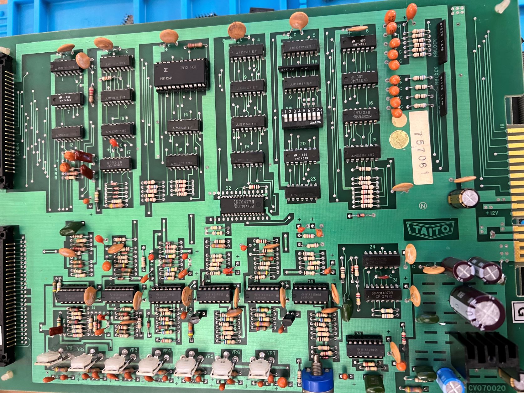
Other areas for concern were the LM3900s which are prone to failure so it seemed like a plan to replace them.

I had already ordered a desoldering gun but that one arrived damaged. A replacement arrived quickly but while it actually worked this time, I wasn't very impressed. The suction was just about adequate and the temperature control was very inaccurate. I did a lot of practicing on old circuit boards and despite VERY frequent cleaning of the nozzle, it constantly blocked. So - I returned that and bought a Hakko instead. What a difference. The suction is great and temperature control seems more accurate.

You still have to clean the nozzle but just not constantly.

So, I removed the old LM3900s, soldered in some double wipe sockets and new LM3900s. The Hakko made this really quite a simple task and it has really boosted my confidence. Here is a pic of the new sockets/chips. I also gave the board a quick clean too.

IMG_3933.JPG


When I powered the old girl up again, it was disappointing that the horrible loud rasping/grating noise was still present from the speaker, together with the slightly corrupt display. But, some of those old 3900s definitely must have been faulty because I can now make out some additional sounds like bombs being dropped, so it was something that needed doing.

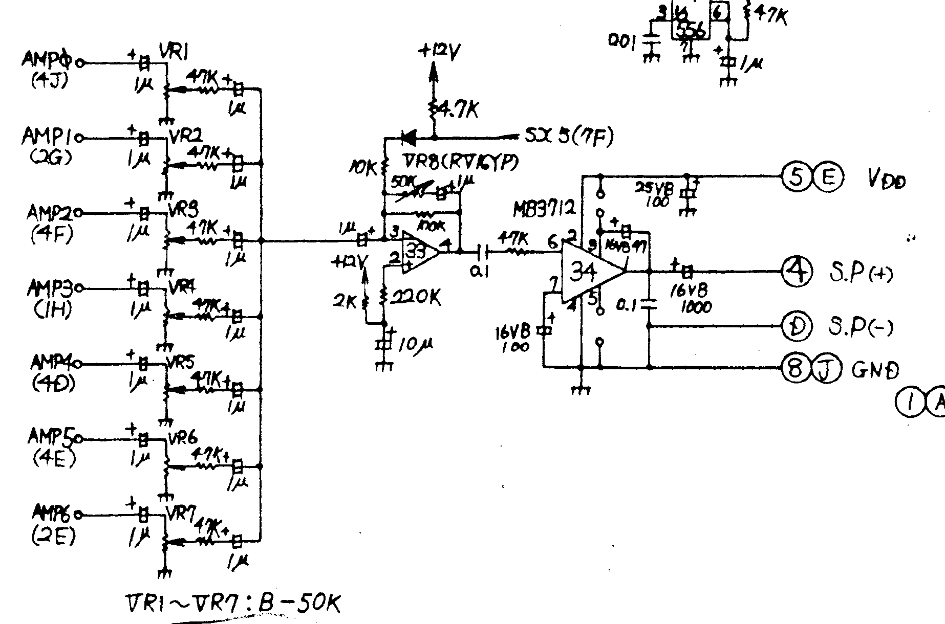
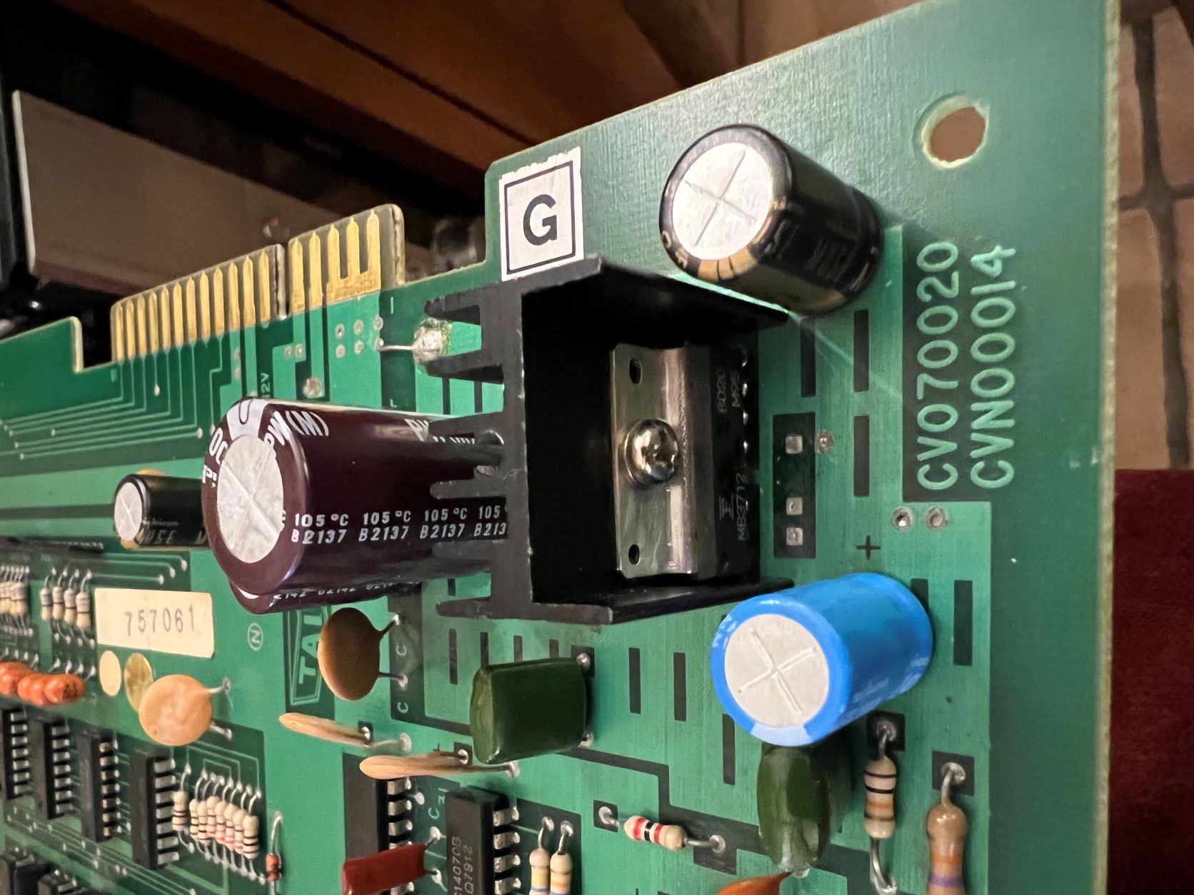
Another suggestion that the audio amp chip (MB3712) might be faulty. These are cheap and readily available so I swapped that out too.

IMG_3951.JPG


I also changed the electrolytic capacitors around the amp area with some decent Nichicon ones.

Well, no difference to the horrible loud noise from the speaker, or the display.

The other suggestions I have been given are to try a different power supply, just in case, and also try connecting up to a TV with a composite input to see if I get a stable B&W image.

I did buy a cheap power supply from Amazon and when it arrived, boy, is it cheaply made. So, I am not sure if is even worth trying. And, I am still waiting on some muscle to arrive to move the only TV I have with a composite input because that is upstairs and my back is still V dodgy!

One other suggestion from RaveN was when I tried the test rom, which seemed to work ok, I didn't put the game eproms in too. I think this was supposed to check the addresses/buffers but I really don't know how to interpret the results.

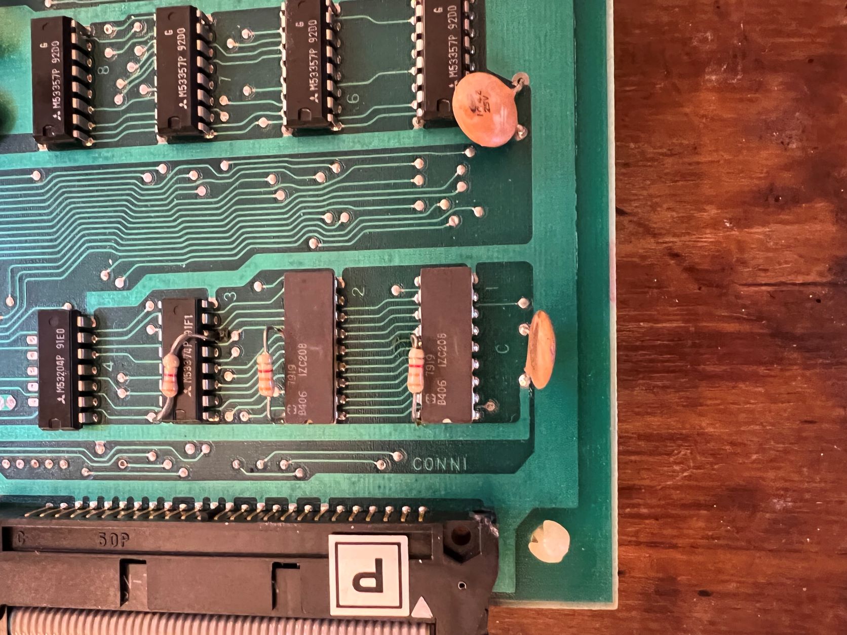
Another suggestion from Patzik was the colour Proms IC 12 & 13 but cannot find suitable replacements to try. They are the 2 chips bottom LH side on this pic (IZC208):

IMG_3948.JPG


As you can see, I am a bit stuck at the moment so any suggestions would be great!

Best regards

Mark

Clabs2022-05-20 15:47:18
 

Lurch666

Active member
Feedback
21 (100%)
Credits
4,142CR
Try running the PCB with the shifter chip (3 on the audio PCB) removed just in case it's causing problems.

You know it's faulty so there's no point in having it in.

The sound FX are activated by the two 74LS174 chips at 14 and 15.You could try testing/replacing them.
 

Clabs

Newbie
vacBacker
Credits
11CR
Hi Lurch and thank you as always for your help.

I have tried with the shifter chip removed and the results are just the same.

With regards to the sound FX chips, if you look at the pic of my sound board, I have M53374p's @ 14 & 15. Would 74LS174 be equivalents? I think it is beyond my ability to test them so I think it would be best to replace them.

Thanks again for all your help :)
 

Lurch666

Active member
Feedback
21 (100%)
Credits
4,142CR
Clabs said:
With regards to the sound FX chips, if you look at the pic of my sound board, I have M53374p's @ 14 & 15. Would 74LS174 be equivalents? I think it is beyond my ability to test them so I think it would be best to replace them.

74LS174 are exactly the same as M53374
 

Clabs

Newbie
vacBacker
Credits
11CR
Hi Bones - thank you for your reply.

By dodgy fan, did you mean electrical interference caused by the fan or just fan noise? The fan is a bit noisy and actually wasn't spinning at all when I first got the table - it was full of horrible muck! I can't see that there is a connector where I can easily unplug the it (I don't want to butcher the wiring if I can help it) but I will have another look later tonight.

Cheers, Mark
 

bones

Active member
Feedback
15 (100%)
Credits
1,626CR
Sort of, not sure if yours is mains or 12v, just thought that if it was 'dragging' somewhere in the 360° rotation it would naturally draw more current at that point every rotation. Unlikely but worth a check. You said you'd recapped it, did you check the tantalum beads as well as the electrolytics. I had a noisy lunar rescue PCB and it turned out to be a tantalum bead near the amp. Good luck.
 

Clabs

Newbie
vacBacker
Credits
11CR
Thanks Bones.

Yeah - I kind of had that thought process. The fan is 100v ac I believe. As you say, it is unlikely but I will have to change that fan anyway so I will cut the wires and insulate them - it will take something else out of the equation.

I did change the 6 electrolytic ones on the sound board because one look a bit bulgy underneath, though they all checked out ok on my little component tester. I then checked all the tantalum beads on all 3 boards. I didn't unsolder any of those, I just checked for shorts with a multi meter. I also checked the diodes both ways with a meter - all seem ok.

I will upload a youtube video that includes the sound. The odd thing is that the noise is really loud, even with the master volume turned right down.

Oh, I also tried running the game with power to the monitor disconnected in case of interference from there - no change to the noise.

Cheers again.
 

patzik

Active member
Feedback
1 (100%)
Credits
322CR
HI Marc,

sorry for the late reaction, was kinda busy with life stuff. Now that you have the 3900's socketed you can troubleshoot the sound part easier (nice job btw).

The sounds are generated in separate pieces, and all come together as AMP0-AMP6 and go to the final amp section. Probably one off these 7 sounds (or more) are bad and first you have to find the troublesome ones. What you could try is turning the VR1 through 7 all the way down, and turn them up one at a time when the game is running, this should give you an indication of which signal is giving the noise. I won't post all the separate pieces of the schematic, but it is very clear and should be easy to troubleshoot. This is the part of the final stage.

Screenshot_2022-05-20_at_20.25.42.png
 

patzik

Active member
Feedback
1 (100%)
Credits
322CR
I took another look at your video on the first page and something dawned on me. The test rom is supposed to test each sound, one after another. However I can hear the saucer hit sound run continuously, and that other sound (the continuous 'beep') might be the extended play sound that is running continuously. I'll have a look at the schematic what triggers them.

Edit...

Bit D4 on the data bus triggers the extend play through a 74ls174 (either ic15 or ic23)

The same bit D4 trigger the ufo hit through another 74ls174 (either ic14 or ic19)

I say either here because I am looking at 2 different schematics and I don't know which one is correct for your board.

This D4 comes from another board, and also goes to the shifter (and could cause graphics issues here). So might be worth looking into, do you have a logic probe?

I'm sure the sound issue is not caused by the fan, or a capacitor or something like that so for now I would not spend time looking in that direction.

2nd edit, you could test this theory by grounding pin 12 on these 74ls174's. If I'm correct then grounding pin 12 on either ic should make one of the sounds disappear. You can do this by attaching a wire to ground and just touching the pin with this wire. I use a wire with alligator clips and attach one end to ground and the other end to a probe lead that I have taken from a multimeter, but anything will do just don't short this wire to something else...

patzik2022-05-20 20:42:00
 
Top