You are using an out of date browser. It may not display this or other websites correctly.
You should upgrade or use an alternative browser.
You should upgrade or use an alternative browser.
PI/Arduino Processor Emulator
- Thread starter andrewsm
- Start date
Probably in a few months I will have them ready to be made to order. My plan would be they come with a full instruction manual. Bit more software to sort out but it is basically working atm. Im using it already to debug boards so its getting a good test.
Been working on a Gang Wars board recently and had an issue with VRAM failing the self test. Out of three VRAMS, only one would consistently pass.

Decided to use this Functional tester that I've developed to see if I can find the fault. First thing I did was create a test sequence for the good VRAM. I already knew which chip that was so simply ran the tester on each pin from 1 to 28 and stored the file. I simply placed the probe on each pin while the tester stored the data from it. Each pin was labelled up and basic device info added.

Next I ran the test on the good chip and it passed all pins. Tjis proved the test was repeatable.
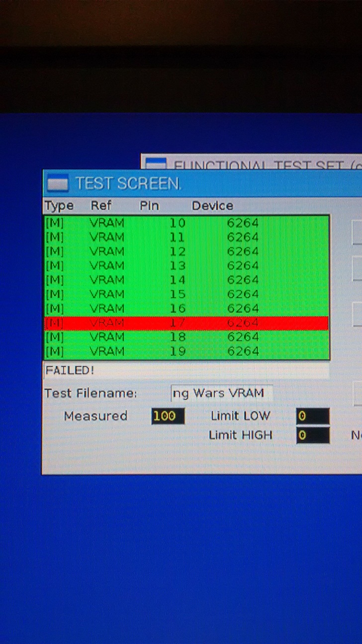
Running the test on the other two devices showed up pin 17 as a consistent fail. Other pins did fail but retesting the pin mainly passed, but pin 17 on both refused to pass as can be seen from the screen shot.
Tracing this pin revealed it was D5 from the processor pin 64.The D5 line was fed via some buffer chips but the input to the buffers had no signal present. Reflowing pin cured it but after a while it came back so a wire-add was inserted. This created a permanent fix
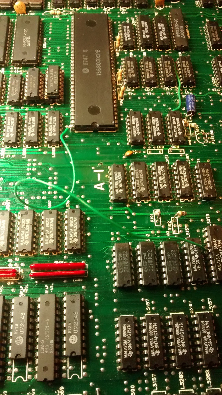
This was tidied up but it did get the board booting.

Success well for some part as now I have sprite issues but at least its now reliably booting up and running the game.
The conclusion of all this is that my tester has proved itself once again that it can identify hard to get faults. Sure probing around with a scope wud prob find it but this made the fault finding a lot quicker and as you can see, found the pin instantly.
Will keep this post updated as time goes on but it looks like this tester is proving itself slowly. Will be making these to order later on so anybody interested then let me know guys. Few things to iron out yet but its working so far.
Decided to use this Functional tester that I've developed to see if I can find the fault. First thing I did was create a test sequence for the good VRAM. I already knew which chip that was so simply ran the tester on each pin from 1 to 28 and stored the file. I simply placed the probe on each pin while the tester stored the data from it. Each pin was labelled up and basic device info added.
Next I ran the test on the good chip and it passed all pins. Tjis proved the test was repeatable.
Running the test on the other two devices showed up pin 17 as a consistent fail. Other pins did fail but retesting the pin mainly passed, but pin 17 on both refused to pass as can be seen from the screen shot.
Tracing this pin revealed it was D5 from the processor pin 64.The D5 line was fed via some buffer chips but the input to the buffers had no signal present. Reflowing pin cured it but after a while it came back so a wire-add was inserted. This created a permanent fix
This was tidied up but it did get the board booting.
Success well for some part as now I have sprite issues but at least its now reliably booting up and running the game.
The conclusion of all this is that my tester has proved itself once again that it can identify hard to get faults. Sure probing around with a scope wud prob find it but this made the fault finding a lot quicker and as you can see, found the pin instantly.
Will keep this post updated as time goes on but it looks like this tester is proving itself slowly. Will be making these to order later on so anybody interested then let me know guys. Few things to iron out yet but its working so far.
Excellent mate, great effort you're making with this bit of kit.
Tune in for another update on this tester chaps.
Despite being pretty hectic with work, I have now added another feature to it which mainly was for my benefit but has proved to be a useful add on.
One problem ive had over time is how to tell if a TTL logic chip is working properly or not. Sure it can be tester by logic probes or scopes but ultimately the device is removed and another fitted, often with no real change to the board. Stuck pins are common and sometimes inputs cause issues. Anyone that debugs boards will know this. Piggy backing sometimes works but it can be a slow process.
This tester apart from everything else it does, will now test most TTL devices on the board while the board is powered up and running. It wont affect the boards operation but will clearly show whether the device passes the truth tables or not. If it fails, a little work is needed in checking the results but if they look ok, then the tester can learn and then get better next time. It will also check for stuck pins and show tied ground pins or pullups.
All data is stored in files which can be backed up on usb sticks etc.
Ive added a few pictures showing the screen shots of it in action.
Test clip over a chip. The clip is a 20way which covers most TTL devices.

Testing a 74LS00 while the board is powered up and running the game. This one passed the tables

Front of the tester showing the Active Device Test screen. Ive called it this as needed to think of something lol.
So far, the tester will now do the following:
1) Actively test most TTL devices on the PCB without affecting the game running. Clocks may be slightly bothered due to the additional cabling.
2) Simulate a Z80 or 8080 processor allowing full data and address control. More can be added as software is improved.
3) When using the processor connection in 2 above, ROMS can be read and dumped into BIN files.
4) Memory maps can be interrogated allowing vital select lines to be toggled.
5) Some RAMs can be written to and read.
6) I/O ports can be checked.
7) Audio signals can be traced using the probe.
8) Built in logic probe clearly showing the state and duty cycle of any pin.
9) Test programs can be generated using a known good board and then applied to faulty ones. Helps identify faults quicker.
Future improvements will include a 2716 and 2708 eprom programmer plus more things as I think of them.
This has developed due to my need to debug Space Invaders etc and has so far helped fix three boards. It is intended to be a stand alone unit which without much technical knowledge allows someone to trace faults. No scope etc is needed but obviously it should be regarded as a tool and hence schematics and some level of skill is needed to take the information it gives and apply it to tracing the faults. Its an ongoing project so improvements are happening all the time.
Depending on the interest this gives, I will be looking to make these to order. The unit will include a Pi3, Arduino, LCD touch screen, and IC tester pod. A manual will also be included and details on all the front connections so the processor connections can be easily made. Aiming to use a two sided PCB as the unit I have is wired manually and a mess tbh. Estimated cost atm is £350.
Cheers
Mark
Despite being pretty hectic with work, I have now added another feature to it which mainly was for my benefit but has proved to be a useful add on.
One problem ive had over time is how to tell if a TTL logic chip is working properly or not. Sure it can be tester by logic probes or scopes but ultimately the device is removed and another fitted, often with no real change to the board. Stuck pins are common and sometimes inputs cause issues. Anyone that debugs boards will know this. Piggy backing sometimes works but it can be a slow process.
This tester apart from everything else it does, will now test most TTL devices on the board while the board is powered up and running. It wont affect the boards operation but will clearly show whether the device passes the truth tables or not. If it fails, a little work is needed in checking the results but if they look ok, then the tester can learn and then get better next time. It will also check for stuck pins and show tied ground pins or pullups.
All data is stored in files which can be backed up on usb sticks etc.
Ive added a few pictures showing the screen shots of it in action.
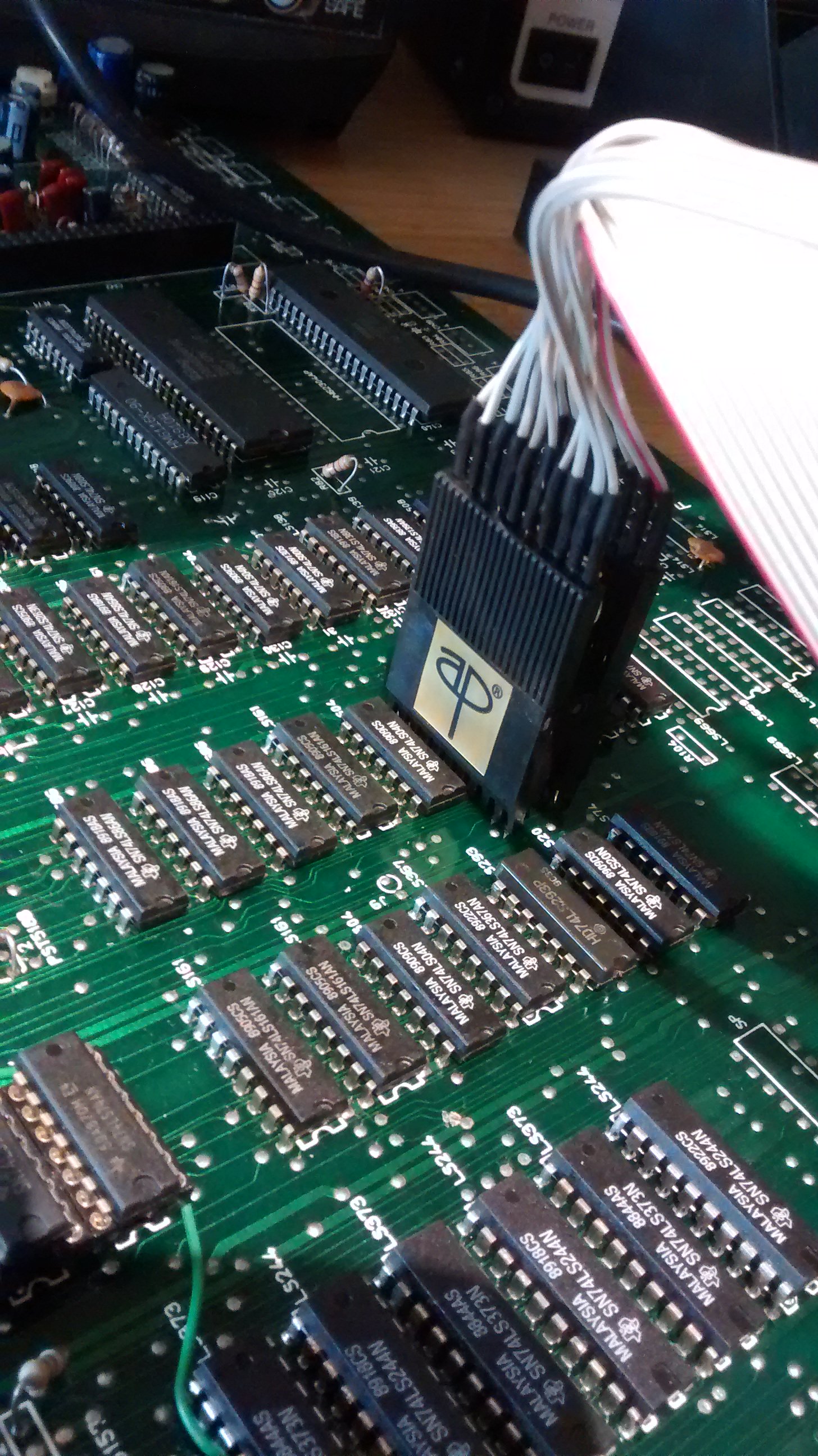
Test clip over a chip. The clip is a 20way which covers most TTL devices.
Testing a 74LS00 while the board is powered up and running the game. This one passed the tables
Front of the tester showing the Active Device Test screen. Ive called it this as needed to think of something lol.
So far, the tester will now do the following:
1) Actively test most TTL devices on the PCB without affecting the game running. Clocks may be slightly bothered due to the additional cabling.
2) Simulate a Z80 or 8080 processor allowing full data and address control. More can be added as software is improved.
3) When using the processor connection in 2 above, ROMS can be read and dumped into BIN files.
4) Memory maps can be interrogated allowing vital select lines to be toggled.
5) Some RAMs can be written to and read.
6) I/O ports can be checked.
7) Audio signals can be traced using the probe.
8) Built in logic probe clearly showing the state and duty cycle of any pin.
9) Test programs can be generated using a known good board and then applied to faulty ones. Helps identify faults quicker.
Future improvements will include a 2716 and 2708 eprom programmer plus more things as I think of them.
This has developed due to my need to debug Space Invaders etc and has so far helped fix three boards. It is intended to be a stand alone unit which without much technical knowledge allows someone to trace faults. No scope etc is needed but obviously it should be regarded as a tool and hence schematics and some level of skill is needed to take the information it gives and apply it to tracing the faults. Its an ongoing project so improvements are happening all the time.
Depending on the interest this gives, I will be looking to make these to order. The unit will include a Pi3, Arduino, LCD touch screen, and IC tester pod. A manual will also be included and details on all the front connections so the processor connections can be easily made. Aiming to use a two sided PCB as the unit I have is wired manually and a mess tbh. Estimated cost atm is £350.
Cheers
Mark
Mark you had my money when you first started posting progress, but this is turning into an amazing piece of kit mate.

I've sent you a PM about this but I just wanted to add how easy it can be sometimes to miss posts like this on the forum.
This is a project I that, along with the arduino in-circuit tested can be a life saver for boards.
Repairers, like myself, should not panic but embrace these tools. You might be able to put a tool in someone's hands but knowing how to use it is the key. If this can make our jobs a bit easier diagnosing hard to determine signal paths then these kind of become the modern day Fluke 9010 and ABI Boardmaster.
We shall call this the FaultSlayer-9000

I've offered my support to both projects in various ways. Hope I can help somehow.
This is a project I that, along with the arduino in-circuit tested can be a life saver for boards.
Repairers, like myself, should not panic but embrace these tools. You might be able to put a tool in someone's hands but knowing how to use it is the key. If this can make our jobs a bit easier diagnosing hard to determine signal paths then these kind of become the modern day Fluke 9010 and ABI Boardmaster.
We shall call this the FaultSlayer-9000
I've offered my support to both projects in various ways. Hope I can help somehow.
silverfox0786
Beware the Hillman
so when you taking my money?

Sorry if im slow getting back with PMs, had a few! Will answer later on, however quickly looking though them there are a few questions raised so prob best to put the answers on here.
1) Can an external display be added.
The unit runs under Linux and is using a Pi3 to do the user stuff. As a result of this there is an hdmi connector and switching between the LCD and hdmi is simple. Instuctions will be given on this.
Note that as its a Pi3, wifi and bluetooth are built in so full internet access is available plus all the usual Pi features. The tester is a app thats simply run.
2) Does it give live updates on logic pins.
The answer is yes. The A.D.T , or Active Device Testing takes effectively a snapshot of the chip under test and graphically displays them. Stored truth tables are then applied to determine if it passes or fails. Stuck pins are detected by change of state. Pins tied to ground or 5V clearly will show as their state but pins which should change and dont will be shown too.
Also i forgot to add before that theres also a basic voltmeter which is enabled when the probe is switched to audio. Nothing major but it will measure most supplies DC on the board.
andrewsm2016-07-10 16:57:20

TheGecko said:
I echo the sentiment of TheGecko
In theory this should be able to be programmed to test LS244/245/373 etc in circuit.
I hate the idea of compile-in for this kind of thing, are device definitions going to be in some folder somewhere so we can all contribute?
That would open the floodgates for 2114 (already does this I know), 5101, 2148, 6116, 6264 etc
Just give us a big enough clip lead and we're sorted.
Battlezone
Active member
Looks like a great bit of kit. Well done for pulling this together.
Thanks for all the comments guys. Im going to start taking orders for the first batch soon. Will update this soon with details for anyone thats interested.
Couple of points, the CPU is a 1.2GHz quad core processor in the Pi and a microcontroller in the Arduino. A logic analyser would be possible by adding some addition circuitry. The problem is that the arduino would not be able to aquire the data fast enough. I have thought on this and have a idea how to do it however its a future add on at the moment.
The files that the tester creates for a device can be viewed and edited by most txt editors. New ones can be created manually by comparing the truth tables.
The sofware will be compiled on the testers however the arduino accepts a variety of low level commands so there is no reason why stand alone unique tests cant be written. These could be ulitimately added to the main tester program in time. A full list of the arduino commands will be given in the manual.
Hope this helps.