Where do you get your IC sockets from? I'll order a batch and practice on a scrap board until I've got it down.And you should replace at least that socket you've taken a picture of it. I recommend using the expensive machined sockets, but at least new double wipe sockets. The socket shown in the picture is oxidized and will not make good contact. Before you start seraching for faulty chips, you should make sure all the sockets and the chips placed into them are in good condition.
But only replace sockets if you are able to: you have to have the right tools and you have to know how to do it. Otherwise you'll ruin the board. I know what I'm talking about because I'm restoring 2 boards for a few weeks now someone else has 'worked' on before. Dozends of traces have been ripped off and just covered by soldering new sockets on. That's a very time consuming work to fix this if you want the board look good again and you don't want to put dozens of jumper wires accross the board.
You are using an out of date browser. It may not display this or other websites correctly.
You should upgrade or use an alternative browser.
You should upgrade or use an alternative browser.
First fix frogger on galaxian bootleg
- Thread starter drbible
- Start date
Usually, I buy sockets from www.reichelt.de / www.reichelt.com. Search for GSxxP (replace xx by the number of pins desired). The much cheaper dual wipe sockets don't have the P at the end.
NivagSwerdna
Active member
IMHO Don't overthink it. Go on EBAY and order some. e.g. https://www.ebay.co.uk/str/ledessential
I don't buy the fancy ones but your mileage may vary... some people swear by round holes... weird really... chip legs aren't round... <flameproof underwear ON>
Have you bought your logic probe yet?
I don't buy the fancy ones but your mileage may vary... some people swear by round holes... weird really... chip legs aren't round... <flameproof underwear ON>
Have you bought your logic probe yet?
That's something I always wonder about, round hole square peg. With chip legs being flat fitting into a round, hole means only the corners rub against the inner part of the hole, though usually very tightly. Dual wipe are sprung and clamp onto both sides of the leg covering a greater area. The spring can give over time, but as long as it's not ultra cheap ones, you'll be fine.
Avoid the single wipe inserts at all costs.
Avoid the single wipe inserts at all costs.
Logic probe obtained, and I've done about 3 hours of you tube cramming about gates, addresses, clock, watchdog, schematics etc (the 101 videos and a yie ar case study). Almost get it now! However I can't get past the power readings on the CPU so thought I'd replace the socket anyway. Going to take a look again today anyway and double double check the voltages while sockets are on order.IMHO Don't overthink it. Go on EBAY and order some. e.g. https://www.ebay.co.uk/str/ledessential
I don't buy the fancy ones but your mileage may vary... some people swear by round holes... weird really... chip legs aren't round... <flameproof underwear ON>
Have you bought your logic probe yet?
NivagSwerdna
Active member
OK... Visit all 40 pins of the Z80. What's occuring?Logic probe obtained
NivagSwerdna
Active member
Again don't over think it at this point. Find a nice +5V for the red and a GND for the black. A capacitor across the power rails may be a good place. Then use your probe to determine HI (5V), LO (GND), Pulsing (changing), Nothing (No connection). Get confident by getting a high on the corner of a 14 or 16 pin device and a lo on the opposite corner. Wander around the board and feel that you have power to most of the bits and pieces.Logic probe obtained, and I've done about 3 hours of you tube cramming about gates, addresses, clock, watchdog, schematics etc (the 101 videos and a yie ar case study). Almost get it now! However I can't get past the power readings on the CPU so thought I'd replace the socket anyway. Going to take a look again today anyway and double double check the voltages while sockets are on order.
For the Z80... see if you can find a chip that is powered nearby... and wander up and down the Z80 pins to see if you have any life there. Call me a cynic but I think it very unlikely you have no power to the CPU.... if you do... maybe try removing it and see if the device was shorting it... i.e. measure to the socket rather than the CPU pins.
If you have checked power, reset and clock, check the data bus next (D0..D7). Every single bit should toggle in any way, if one or multiple are static (stuck high or low), there seems to be a problem. Maybe on the CPU or on any other device attached to the bus.
CPU info:
Clock at pin 6 = permanent hi
Reset at 26 = permanent lo
5v at 11 = lo measurement from the chip leg. However this shows as hi from the socket connector without the IC installed.
Also checked the voltages and 5v on underside of the board and in socket connector pins 11/29. However when measured at the chip it is negligible.
Presumably this is wrong and the IC leg isn't connecting properly or does the CPU voltage vary depending on what it is doing.
If not then I need to put a new socket on before investigating the clock circuit / reset signal etc.
I did try another (equally old) z80 and readings were the same.
I need to get this board onto a bench as it's still in the machine and the wiring burnt out this weekend which wasnt a good moment. See pic of burnt dodgy connector - need to wire a safer connector than this. What would anyone advise using instead of this for connecting the board up to a tv and a power source at a test bench and also ultimately for replacing this pin out in the machine if/when it ever makes it back in there.
NivagSwerdna
Active member
Get it out onto the bench and give it a nice clean 5V then take stock.... it was partially working not long ago so it should not have all self destructed just like that.
Once you are settled... trace the clock back... look at 1E pins 4 and 5... you should have 6MHz...

then follow this forward to the horizontal video...

You should have a clock at pin 5 of 6C
That should appear at...
the buffer at 8D

go in pin 14 and out 13... and into the CPU socket.
Trace that through and see how you go.
Once you are settled... trace the clock back... look at 1E pins 4 and 5... you should have 6MHz...
then follow this forward to the horizontal video...
You should have a clock at pin 5 of 6C
That should appear at...
the buffer at 8D
go in pin 14 and out 13... and into the CPU socket.
Trace that through and see how you go.
NivagSwerdna
Active member
>>>or does the CPU voltage vary depending on what it is doing.
With a decent power supply you should expect a steady 5V or 4.9 or 4.8 perhaps... aim for as close to 5V as you can get. It should not sag.
With a decent power supply you should expect a steady 5V or 4.9 or 4.8 perhaps... aim for as close to 5V as you can get. It should not sag.
You needn't to proceed until you have the correct voltage at the supply pins of the ICs (especially cpu) and having a working clock signal at pin 6 of the cpu. If there's no clock signal, go back to the oscillator (1st schematic digram above) - watch pin 7 of the 74368. If there is no activity, there won't be activity on any point later in the clock chain. If the oscillator isn't working, suspect the 74368 and the quartz. Despite it is not very prone to fail, check C32 as well. If you have activity there, then go on checking 7407 / pin 3 and pin 6, the clock signals of the 7474 flip flops (pin 3 / pin 11) and the utputs of the flip flops (pn 5 / pin 9). So proceed until you get to pin 14 / 74367, if ok, check pin 13 also. If the activity stops at one point in the line, you've found the faulty IC.
The board you have, is a conversion of galaxian to frogs I think. In the conversion process some of the trace are cut intentionally and some stuff is jumped to shift addressing and maybe change the nmi. So repairing the cut traces will not help you, and will keep the board from running the frogs software.
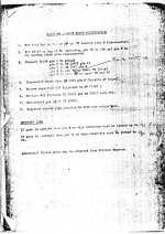
Sorry to hijack a thread, but do you have any more paperwork like this, maybe for other conversions too ?.Here are the instructions for the conversion, check that the tracks you repaired really needed to be repaired...
Item 4 is hard to read but this is ic 2N
I have often imagined this sort of thing must exist somewhere, and this is exactly as I pictured it.
Yes I did wonder about this when i repaired two broken chip pins at 2B and 6E pin. The pins around them look quite corroded though so I figured these weren't snipped.The board you have, is a conversion of galaxian to frogs I think. In the conversion process some of the trace are cut intentionally and some stuff is jumped to shift addressing and maybe change the nmi. So repairing the cut traces will not help you, and will keep the board from running the frogs software.
OK been looking at this today.Get it out onto the bench and give it a nice clean 5V then take stock.... it was partially working not long ago so it should not have all self destructed just like that.
Once you are settled... trace the clock back... look at 1E pins 4 and 5... you should have 6MHz...
View attachment 1932
then follow this forward to the horizontal video...
View attachment 1933
You should have a clock at pin 5 of 6C
That should appear at...
the buffer at 8D
View attachment 1934
go in pin 14 and out 13... and into the CPU socket.
Trace that through and see how you go.
I've replaced the IC socket for the z80 and there's now a clear 5v reading on pin 11/29. De soldering it with my basic kit was a pain but went fine after much practice on a scrap board. Chip sits nicely in the new socket anyway. First vague sense of achievement on this!
So, looking at the clock circuit, 1E pin 4 is nothing although the logic probe picks up a scratchy signal if moved around on the pin. Pin 5 is constant low.
6C pin 5 same as clock pin 4....pretty much nothing but slight sign of life.
8D 14 nothing, 15 low.
CPU pin 6 hi but a different tone to normal hi.
Reset still constant lo.
This is all presuming my logic probe could pick up a valid clock signal. I think it could as there's 4 pins at 6T that oscillate when probed.
Replace the 74368?
How do I check the crystal with basic kit?
I was thinking the same thing, there are a lot of bootlegs and conversion, but documentation is hard to find. I got this from https://arcarc.xmission.com/Tech/Hardware Mods and Info/Sorry to hijack a thread, but do you have any more paperwork like this, maybe for other conversions too ?.
I have often imagined this sort of thing must exist somewhere, and this is exactly as I pictured it.
and there are some more documents here of conversions.