You are using an out of date browser. It may not display this or other websites correctly.
You should upgrade or use an alternative browser.
You should upgrade or use an alternative browser.
Arduino In-Circuit Tester: Build Project
- Thread starter Judder
- Start date
I think I've sussed it. I didn't get time to test it yesterday but it looks like I've ended up with my head pcb the opposite way round to your pictures which means all the ground pins would have been connected to the cpu socket. I've got it the right way round now and everything checks out ok. I'm hoping to get time to test it this afternoon.
I've been trying to implement 6802 to test a Williams sound board.
I have it up and running after a fashion but the Bus test always reports D0 as being bad on a working sound board.
Given that the clock generation circuity is part of the 6802 itself how do I implement timing for reading and writing data via the E pin?
I'm also wondering about the best way to implement testing the 6821, should be a readwrite RAM region or input and output?
guddler said:I think I've sussed it. I didn't get time to test it yesterday but it looks like I've ended up with my head pcb the opposite way round to your pictures which means all the ground pins would have been connected to the cpu socket. I've got it the right way round now and everything checks out ok. I'm hoping to get time to test it this afternoon.
I was struggling there yesterday as well and I couldn't see any explicit instructions on connecting the two halves together. I ended up zooming in of the pictures on Paul's site and orientating my unit and ribbon cables to be the same as Paul's. I ended up with the in a working state but not exactly the same as they had been before I checked.
I was a bit puzzled because I used Judder's pics so my cable was exactly the same as his. A bit odd but serves me right for being lazy and not working out eh pinout properly. If I now compare what I have to Paul's pics, I can see that the head part on mine is effectively upside down. Not really a problem, it appears to be working now.
Having said that, I appear to have the same problem as you with D0, mine reports bad but I'm not using a known good board. I've switched to a known working board but this one is a bootleg Asteroids which doesn't have test points so I need to find out where to solder a link to disable the watchdog because of course now bus test is (understandably) bitching about the reset line.
I'll report back when I've got the known good board sussed out. Once I've done that I'll be able to complete the ROM test and do a pull request for Asteroids too...
guddler said:Having said that, I appear to have the same problem as you with D0, mine reports bad but I'm not using a known good board. I've switched to a known working board but this one is a bootleg Asteroids which doesn't have test points so I need to find out where to solder a link to disable the watchdog because of course now bus test is (understandably) bitching about the reset line.
I did do some testing yesterday with a pair of Galaxians boards, both were non runners, on reported RAM issues and the other ROM issues, but I didn't see the D0 problem there.
Given I've created the 6802 code myself and C++ is not really my thing I'm amazed it does anything.
I chose to look at the Williams sound boards as they are nice and simple. Some ROM, RAM and IO (by way of a 6821) no bank switching and no watchdog.
What i'm struggling with is how to generate the clock in the Ardruino as it all is generated in the (now missing) 6802 chip with just an XTAL across pins 38 and 39.
I'm not sure yet on generating clocks on the 650x series I haven't got to that point. If you look at the code for Star Wars then I believe Paul has done it in there.
[EDIT] Sorry, you're not talking about 650x so doubly not sure yet

I was wrong with my bus issue incidentally. My "POD" head was still jumpered for Z80. Now it's setup correctly I'm getting "E:A0 f7ff" am going to go into the code now to see what that's trying to say and troubleshoot. RAM tests work so I assume it isn't a board fault, although it's possible.
guddler2016-01-24 17:44:42
[EDIT] Sorry, you're not talking about 650x so doubly not sure yet
I was wrong with my bus issue incidentally. My "POD" head was still jumpered for Z80. Now it's setup correctly I'm getting "E:A0 f7ff" am going to go into the code now to see what that's trying to say and troubleshoot. RAM tests work so I assume it isn't a board fault, although it's possible.
guddler2016-01-24 17:44:42
guddler said:I was wrong with my bus issue incidentally. My "POD" head was still jumpered for Z80. Now it's setup correctly I'm getting "E:A0 f7ff" am going to go into the code now to see what that's trying to say and troubleshoot. RAM tests work so I assume it isn't a board fault, although it's possible.
Funny you should say that, about 30 minutes ago I realised that I'd done the same. Haven't re-tried it yet though.
Note to Paul ... the jumpers are will buried inside the UUT plug so there's no reminder that they are there and even if you remember you have to unplug one of the cables to get to them If there are any more hardware revisions can they be moved somewhere easier to get to of it doesn't make the PCB any bigger?
guddler said:I was a bit puzzled because I used Judder's pics so my cable was exactly the same as his.
Ah - good point
Looking at Paul's pictures it appears that his leads have a plug upside down to mine so the lead nearest to the Arduino screen should be the one snug to the edge of the ROM adapter
Guddler - any photos of yours connected the right way?
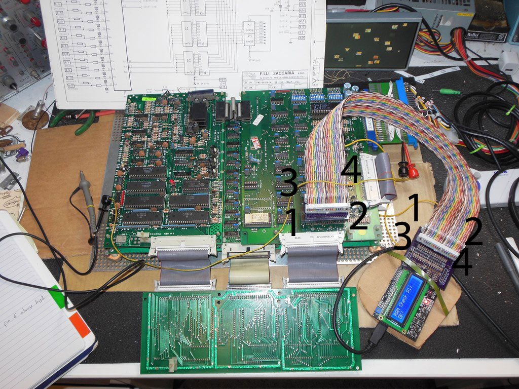
I was studying this picture but your eyes go a bit fuzzy after a while with all the colours...

[edit] Labelled as I think they should be
Judder2016-01-24 20:18:09
I have a picture on my phone that I took. I'm back up the shed for an hour or so now so I can setup access to my repo from my workbench. That will make things a little easier (when the weather is warm enough). Once I'm back down in the house I'll upload the pic.
Have looked at my code and now understand what my BUS error is telling me, so now I need "just" need to see why it's telling me that A11 is stuck low when RAM and ROM tests work. Looking at the schematics vs. what the board does, I have to say, it's perfectly possible it's not lying and A11 is indeed stuck low
Have looked at my code and now understand what my BUS error is telling me, so now I need "just" need to see why it's telling me that A11 is stuck low when RAM and ROM tests work. Looking at the schematics vs. what the board does, I have to say, it's perfectly possible it's not lying and A11 is indeed stuck low
Regarding the cable. Bottom line is there's no real substitute for checking it with a meter.
When I say "beep" below, I mean 470 ohms (and mine reads around 420 Ohms - although the battery light is on in my meter)
Pin 1 on the CPU should beep out to pin 14 on the Arduino (top left of the shield as the keypad is the correct way up), pin 2, CPU = pin 16, Arduino. Pin 40 of the CPU = pin 15 of the Arduino, pin 39 of the CPU = pin 17 of the Arduino.
Just checking those 4 would be enough to make sure you are correctly orientated.
PaulSwan said:You can leave the bitmasks 0x00 if the data is don't care.
Just thought I'd update this. Not to be picky, just so that it's here for anyone else. But...
I hadn't looked into it, but I wondered why my "Write Outputs" menu only had one entry despite me adding a bunch of outputs. I'd quickly gone over the defined array and couldn't see anything wrong.
Now I've got something on the bench to play with I can look at it properly.
Because the code for the output write says this:
if (key == UP_KEY)
{
if (m_outputRegion[m_outputWriteRegion+1].activeMask != 0)
{
m_outputWriteRegion++;
}
}
(Note the check for activeMask being non-zero)
You need to make sure that a write where the data is "don't care" is in fact 0xff or the code will think it's reached the last entry in the menu and not let you go up any further. Consequently because my very first entry in my array of outputWrites had an activeMask of 0x00 (don't care) it effectively killed off the rest of my menu.
Still can't get the bus test to work with the data bus enabled. When I do I get 'E: D0 41', if I disable all the other bus tests and just test the data bus with the UUT plug disconnected I still get it.
There can't be anything wrong with cabling as it was quite happily doing ROM test on Galaxian yesterday.
I can now do a ROM test on a a Defender sound board, however, D6 seems to be stuck high (but this is a working board). Not sure where to go next.
I might dig out my fluke and do some testing of the boards I'm working with so I have known good results.
Well, I'm done for the week now as I'm away working most of this coming week. I may get time tomorrow night but in reality I'd rather not rush it.
I don't know if this would help you, but it may be worth going back to basics and writing a completely new sketch that just toggles a CPU pin, high / low for a given period and checking it on a scope or logic probe. If you want to be fancy, do it on all 40 pins of the CPU and the 8 additional ones, advancing each time any key is pressed on the keypad.
In my case I think that will help me because the behaviour I'm seeing on Asteroids could genuinely be explained by A11 not being able to be driven high and it's now got me thinking that I may have a dry joint or some other soldering or cable issue. As well as my bus test I'm audio outputs that don't activate even when you toggle them, I'm seeing the incorrect ROMs being read and even though I'm passing RAM tests, it could very easily be reading the same RAMs all the time and not really reading all of them. How would the tester know?
On Asteroids, A11 plays a part in pretty much all of that. So maybe I should just listen to the tester and investigate the non drivable pin on the bus test before jumping to the conclusion the test isn't working
Since Judder asked, heres my tester. No blinding colours on the cable because I already had some lying about. And it's not all that long either because it's all I had.
Note that every connector has a strain relief clip on it so the cable loops over the top and in from the left or right (in from the left on the connectors on the left in the picture and vice versa). I also bought a funky little case for £6 too. I can't fit the lid on thanks to the stupidly short pins on the LCD but at least I don't have to worry about shorting anything out.
guddler said:Since Judder asked, heres my tester. No blinding colours on the cable because I already had some lying about. And it's not all that long either because it's all I had
Looks great BTW

One thing I found with mine is if you fit the LCD and the Shield together before you connect them to the Arduino, you can actually sit the 'V' of the shield underneath the LCD screen V connector and before the LCD circuit board so that they fit together fairly tightly and lock together
Days of Lego obviously paid off...
I had a very quick look at my tester at lunchtime. I modified Arduino's "blink" example to toggle pin 52 instead of pin 13 (which on 6502 is A11, hence 0xf7ff in the bus error). I then used an LED on the end of 2 wires and sure enough, no blinking at the CPU end. A very quick trace back showed blinking before the resistor but not after. Modifying the pin to 50 confirms that a good pin does indeed blink the resistor, in other words 470 Ohms plus whatever value was already soldered in to the wire of the resistor was not to much to prevent the eLED lighting, so blow me, i have a faulty resistor brand new out of the pack. Wasn't expecting that. But the good news is, when I next get time to play with this, I'll be in business by the looks of it

So my Arduino ICT was used to fix itself
So my Arduino ICT was used to fix itself
I'll try and answer everything mentioned above:-
Re: The cable hookup
- I'll make a note to take a picture of the cabling to be clear on the cable connection and which way round things go.
Re: The jumper placement
- The consideration was to keep the probe head as small as possible so that it doesn't foul other components next to the CPU on the board. It's easy to change if you want the Design Spark source files to make a different layout.
Re: The bus test.
- The bus test simply puts the Arduino pins into input-pullup mode and reads back the value to determine if it's 0xFF as expected. The pullup is very weak - some boards with some buffer configurations overload the pullup causing the bus test to fail. As a result, this needs to be a per-game setting to determine if it's a valid test or not.
Re: 6802
- I'll try and check the datasheet and report back.
Please feel free to use the Issues tab on the repo for questions")
Paul.
Re: The cable hookup
- I'll make a note to take a picture of the cabling to be clear on the cable connection and which way round things go.
Re: The jumper placement
- The consideration was to keep the probe head as small as possible so that it doesn't foul other components next to the CPU on the board. It's easy to change if you want the Design Spark source files to make a different layout.
Re: The bus test.
- The bus test simply puts the Arduino pins into input-pullup mode and reads back the value to determine if it's 0xFF as expected. The pullup is very weak - some boards with some buffer configurations overload the pullup causing the bus test to fail. As a result, this needs to be a per-game setting to determine if it's a valid test or not.
Re: 6802
- I'll try and check the datasheet and report back.
Please feel free to use the Issues tab on the repo for questions
Paul.
Re: The bitmask
- I should have read the code myself again
Re: Self test
- A simple one could be added based on simply connecting 1-20 to 40-21 on a test socket.
6802
- It looks like since the CPU generates the clock on "E" you don't need a separate external master clock like 6809. You can just drive "E" from the CPU like the 6502 CLK outputs (i.e. the 6502 example is a closer fit to what you want than the 6809 example is). The two 6802 XTAL inputs can be set to input and ignored.
Paul.