You are using an out of date browser. It may not display this or other websites correctly.
You should upgrade or use an alternative browser.
You should upgrade or use an alternative browser.
Arduino In-Circuit Tester: Build Project
- Thread starter Judder
- Start date
Hey guys, I've just started to put my own tester together and came across a smallish issue. Thought I would mention the problem and the fix.
It's probably something very simple for you Arduino guys, but for an inexperienced user like me took me a bit of time to figure it out
Basically I purchased a SainSmart Arduino and a compatible LCD module. The LCD was labelled "Drive the Future". I think this is classed as a "Robot" shield
I compiled the code and uploaded it as per Paul's instructions but I could not get the keys to work apart from "Right" and "Reset". I initally thought the shield was faulty however I tested this out and it was ok.
Looking into this, the keys are defined in
ArduinolibrariesDFR_KeyDFR_Key.cpp
e.g.
ifdef DF_ROBOT_V1
static int RIGHTKEY_ARV = 0; //that's read "analogue read value"
static int UPKEY_ARV = 98;
static int DOWNKEY_ARV = 254;
static int LEFTKEY_ARV = 407;
static int SELKEY_ARV = 638;
static int NOKEY_ARV = 1023;
#else
static int RIGHTKEY_ARV = 0;
static int UPKEY_ARV = 144;
static int DOWNKEY_ARV = 329;
static int LEFTKEY_ARV = 505;
static int SELKEY_ARV = 742;
static int NOKEY_ARV = 1023;
Now it says the Robot is defined but these values would not work for me so I had to figure out a way to output the values which were on mine, as I had no idea what they were. I could then comment out the #else values and define my own.
Using the example (1) on this website I modified the code to do just that using the code for each button:
lcd.print(analogRead(0));
Anyway I've attached the sketch that I've modified so it will allow you to test your LCD and will also give you the analog values for each key press if someone has the same issues
Hope it helps!
https://www.ukvac.com/forum/data/uploads/665/sketch_feb22a.zip
Purity2017-02-23 23:23:05
For 6502 Asteroids I'm going to take a look through Guddler's Asteroids code and get acquainted with it. I see by the comments it's a WIP from a year ago but an awesome foundation.
https://github.com/Guddler/arduino-mega-ict/tree/asteroids/libraries/C6502Cpu
https://github.com/Guddler/arduino-mega-ict/tree/asteroids/libraries/C6502Cpu
PaulSwan said:I've updated the table on the page to include the missing ones.
Thanks,
Paul.
Thanks Paul
I don't want to seem as though I'm teaching people to suck eggs, and apologies if it comes across like that, but I thought it was important to highlight info about the orientation of the ribbon cables.
It became an issue for me because I could see a difference in the orientation on images of peoples builds online, and surely they all can't be correct")
So I'm pretty sure that this is the pinout on both the header and shield. Paul kindly took some hi-res images for me and it seemed to confirm this. So J2<->J6, and J3<->J7

The rainbow ribbons that Alex linked to on the first page has a tab so use that to make sure your orientation is correct. So if the orange circled pin is pin 1 on the shield it needs to be the same orientation and pin 1 on the header pcb using the other end of the ribbon cable.
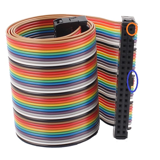
If you get this the wrong way round you are likely to cause a short and
it will cause your ribbons to smoke and possibly die, and possibly other things, so another reason
for this post.
Hope it helps and makes sense!
Purity2017-03-01 17:56:19
It became an issue for me because I could see a difference in the orientation on images of peoples builds online, and surely they all can't be correct
So I'm pretty sure that this is the pinout on both the header and shield. Paul kindly took some hi-res images for me and it seemed to confirm this. So J2<->J6, and J3<->J7
The rainbow ribbons that Alex linked to on the first page has a tab so use that to make sure your orientation is correct. So if the orange circled pin is pin 1 on the shield it needs to be the same orientation and pin 1 on the header pcb using the other end of the ribbon cable.
If you get this the wrong way round you are likely to cause a short and
it will cause your ribbons to smoke and possibly die, and possibly other things, so another reason
for this post.
Hope it helps and makes sense!
Purity2017-03-01 17:56:19
Good call Ben

Guddler and I had some fun with this exact issue initially as my first photo had the board the wrong way up, so I made the following to double check

and Guddler did a nice side shot of his to show the same setup

Hope that helps also - just for reference - and the way I remember it is that the outer connector on the shield (1 2 in my photo) connects to the header side where you still have a row of pins visible from the underneath
Guddler and I had some fun with this exact issue initially as my first photo had the board the wrong way up, so I made the following to double check
and Guddler did a nice side shot of his to show the same setup
Hope that helps also - just for reference - and the way I remember it is that the outer connector on the shield (1 2 in my photo) connects to the header side where you still have a row of pins visible from the underneath
The Last Bandit
User
Any reason not to use boxed IDC headers ?

The Last Bandit2017-03-01 20:13:19
The Last Bandit2017-03-01 20:13:19
IDC headers are fine if you know the orientation and pinout
 , and that was the problem
It's obvious on the header PCB, but not so obvious on the shield
Can't use IDC headers if you don't know which way round they should go

Now that it's clear what pins are what you can easily use IDC headers to make sure the correcting pins are going to each other - good idea
Purity2017-03-01 20:35:00
It's obvious on the header PCB, but not so obvious on the shield
Can't use IDC headers if you don't know which way round they should go
Now that it's clear what pins are what you can easily use IDC headers to make sure the correcting pins are going to each other - good idea
Purity2017-03-01 20:35:00
Since this is a 6809E you'll need to find the first clock stage so you can use clock mastering. Typically it's a 74xx04 somewhere new the crystal (if it has a crystal) or near to the oscillator IC (if it uses one of those).
You'll need to remove the IC and socket so you can replace that clock with one from the tester. Then it's a matter of adding in the game description.
Paul.
You'll need to remove the IC and socket so you can replace that clock with one from the tester. Then it's a matter of adding in the game description.
Paul.
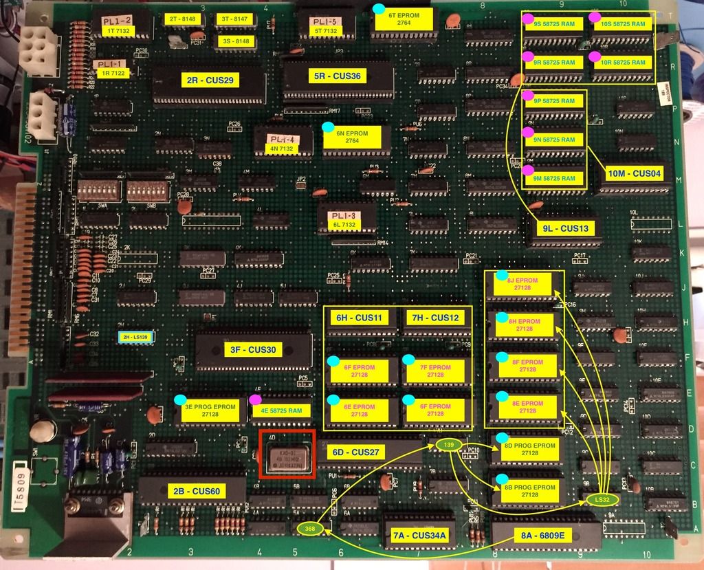
Thanks Paul, there's an oscillator at 4D (see red square on pic). You want me to socket it and when I hook up the Arduino I should remove it and have the arduino run the clock signal? Is there a wire I need to run to the socket or is it all done through the ICT header?

Paul, do you have a video or something that can explain one of the game implementations in this?
I really want to contribute, and am willing to put the effort and time in, but I'd just like something like the Star Wars implementation explained. It'd be great to see where you got the info for the ram / rom addresses etc.
I've got a list of games I'd like to see supported so I'd like to get involved with bringing those games to the tester. Pac-land (Galaga & Mappy are the same hardware) and Asteroids are my current number 1.
Nes4life2017-04-16 20:27:55
That is an oscillator - to be sure it's the right one MAME usually carries and indication of the processor speed that should be some divisor of that. For example, in the MAME driver, "pacland.cpp" (from the MAME source code package), this line shows which oscillator applies to the 6809E:
MCFG_CPU_ADD("maincpu", M6809, XTAL_49_152MHz/32) /* 1.536 MHz */
Also in that file you'll see the memory map for the ROMS, RAMS & IO addresses etc. A similar format is used in the game descriptions in the tester software.
Because the oscillator is awkward to remove due to the hidden pins and is rare to replace, it's usually easier to find the IC that the clock out is connected to nearby and cut that out instead. If you're lucky, it might go to a custom that's already in a socket. Bend out the clock input pin on the IC and attach it to a fly lead from the aux connector on the ICT shield (same as Star Wars, J14 AUX pin 8 (next to the 2-pin GND pin)).
The games are added by defining their description, e.g.
https://github.com/prswan/arduino-mega-ict/blob/master/libraries/CZ80Cpu/CGalaxianBaseGame.cpp
I've chosen to do base platforms and then define games that run on them but you can choose to simply put the descriptions all in one for simplicity. You can ignore interrupts & customs functions to get started and just plumb in ROM & RAM to get going.
Paul.
Stickied

As an ICT this tester could probably be extended to also work as a Signature Analyser right?
Used with an additional single pin probe attachment it could request the user place the pin at specific points on the board, read the signature produced by a known pattern and then confirm if it's as expected. The advantage here is that it could probably pinpoint a failed component. It'd be like an Atari Catbox.
Good idea or too much hard work?
Nes4life2017-04-18 21:59:47
Purity said:I've just started to put my own tester together and came across a smallish issue. ... SainSmart Arduino and a compatible LCD module... I've attached the sketch that I've modified so it will allow you to test your LCD and will also give you the analog values for each key press if someone has the same issues. Hope it helps! https://www.ukvac.com/forum/data/uploads/665/sketch_feb22a.zip
Thanks Purity! The buttons on my LCD now work properly!
