I've never looked into this project properly so am not sure exactly how many I/O pins are used but a Teensy 3.5 has 58 digital I/O, 5v tolerant, default clock is 120Mhz, 512K flash, 256K ram and is Arduino dev compatible. The form factor would need some conversion but may be worth a look. I have used the Teensy's a lot and found them to be reliable and fast.wondras said:I'm having trouble getting the math box and VSM tests to work reliably. I think it's because they use 3 and 12 MHz clocks that are normally synchronous with the CPU clock. The ICT is slower and asynchronous, so it can't send a short enough write pulse at exactly the right time. Maybe I'd have better luck using the ICT's master clock mode, which I haven't tried yet.
You are using an out of date browser. It may not display this or other websites correctly.
You should upgrade or use an alternative browser.
You should upgrade or use an alternative browser.
Arduino In-Circuit Tester: Build Project
- Thread starter Judder
- Start date
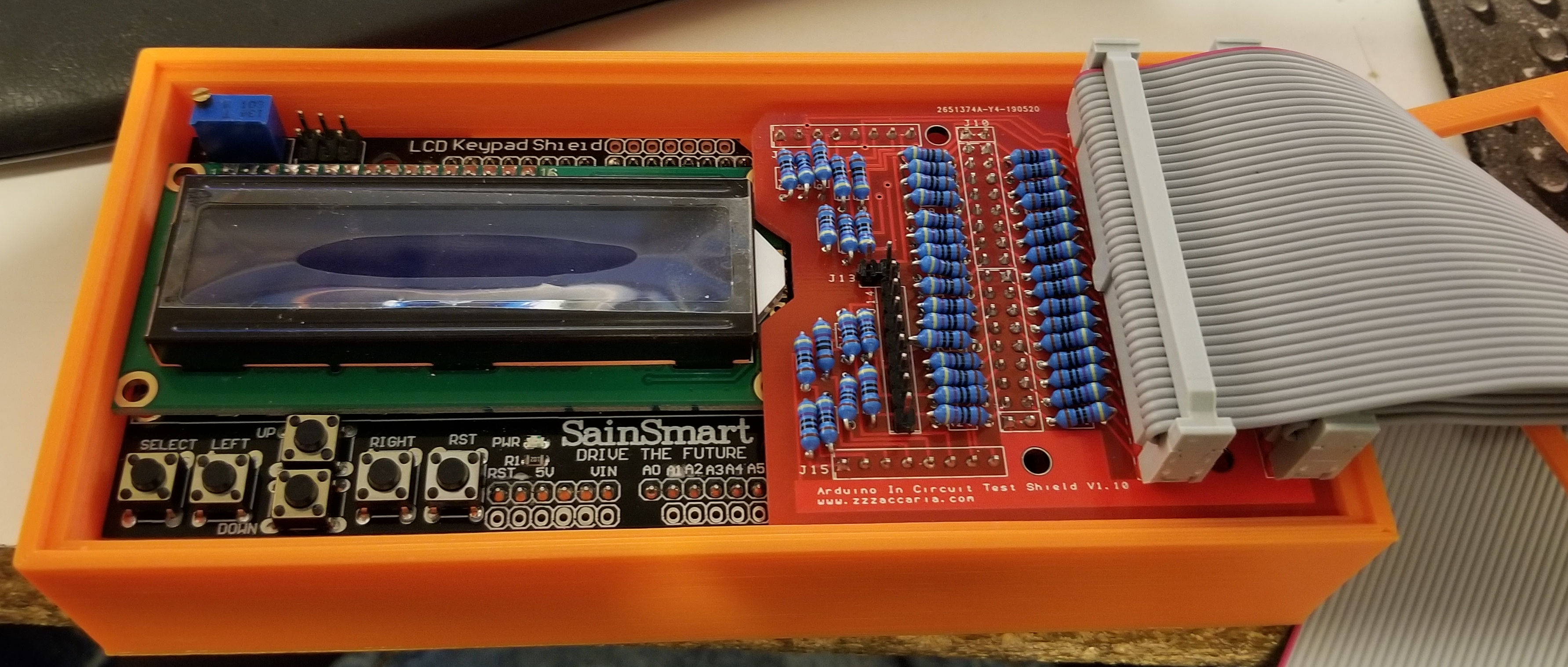
Well, I got my PCB's in today and built the Shield and I've run into an issue...
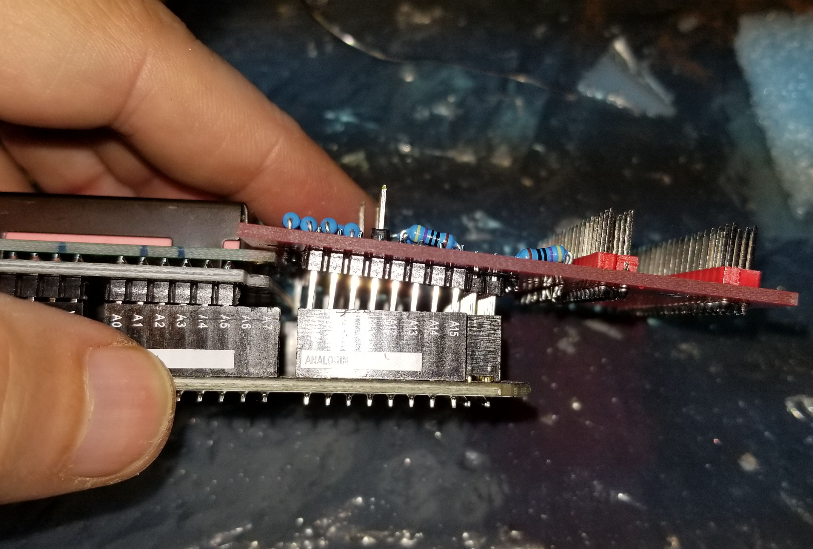
Are different Ardunio's made slightly different than others?
I'll have to see if I can find some Header extenders.
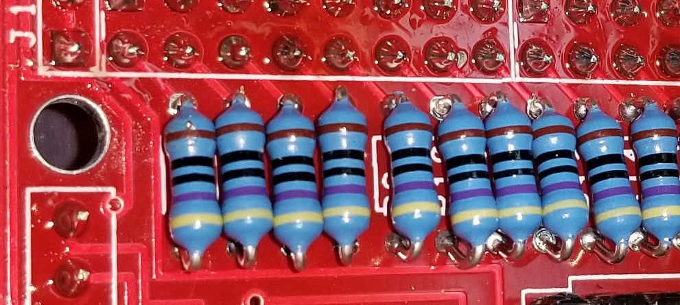
The other thing I would like to see changed is the resistor hole distance increased. Right now the distance between the holes is slightly less than the width of the resistors with the wires bent at a 90 degree angle. So this means one end of the resistor gets bent under or the resistors.
Arcadenut2019-05-28 07:55:01
Are different Ardunio's made slightly different than others?
I'll have to see if I can find some Header extenders.
The other thing I would like to see changed is the resistor hole distance increased. Right now the distance between the holes is slightly less than the width of the resistors with the wires bent at a 90 degree angle. So this means one end of the resistor gets bent under or the resistors.
Arcadenut2019-05-28 07:55:01
Hey Arcadenut... yes the header PCB and the lcd don't fit very well into the Arduino. You can however interlink them so they fit. Header slightly in first, then the lcd at an angle... then push both in together. They do slot awkwardly but make all the necessary contacts.
Yeah the resistor holes aren't perfectly placed either and the next version could do with them slightly wider apart.
As for the 68000 header... I don't know what the BOM is as it's not been listed. I too would like to know the cap value and what the ICs are!Nes4life2019-05-28 08:42:49
Yeah the resistor holes aren't perfectly placed either and the next version could do with them slightly wider apart.
As for the 68000 header... I don't know what the BOM is as it's not been listed. I too would like to know the cap value and what the ICs are!Nes4life2019-05-28 08:42:49
Arcadenut said:Also, do the ribbon cables have to be twisted pair?
I purchased regular ribbon cables....
That's fine. I use regular ribbon cables too.
I ordered these:
https://www.amazon.com/gp/product/B00C0Q5XZ4/ref=ppx_yo_dt_b_asin_title_o00_s00?ie=UTF8&psc=1
I am going to replace the headers on the Shield that plug into the Arduino. That should make them fit better.
https://www.amazon.com/gp/product/B00C0Q5XZ4/ref=ppx_yo_dt_b_asin_title_o00_s00?ie=UTF8&psc=1
I am going to replace the headers on the Shield that plug into the Arduino. That should make them fit better.
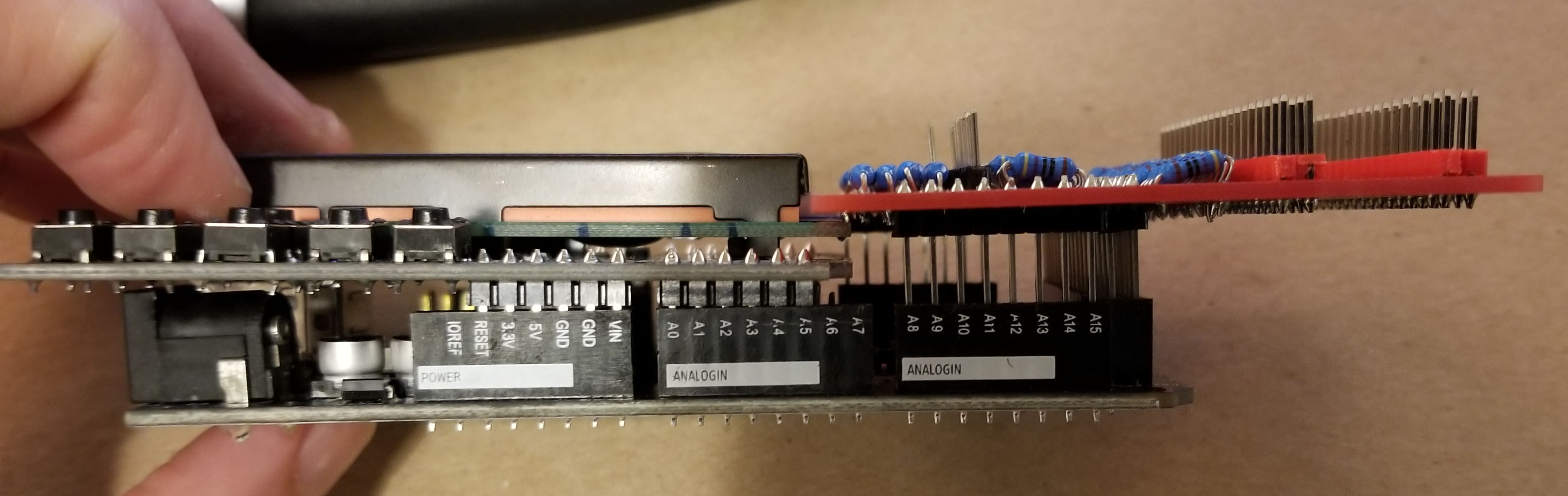
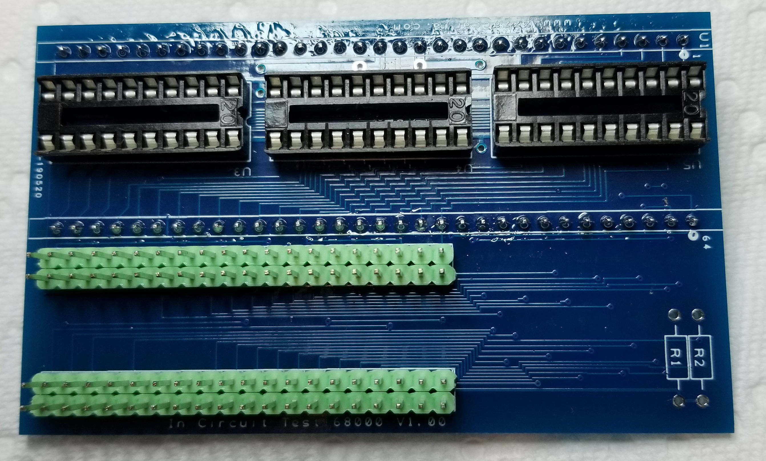
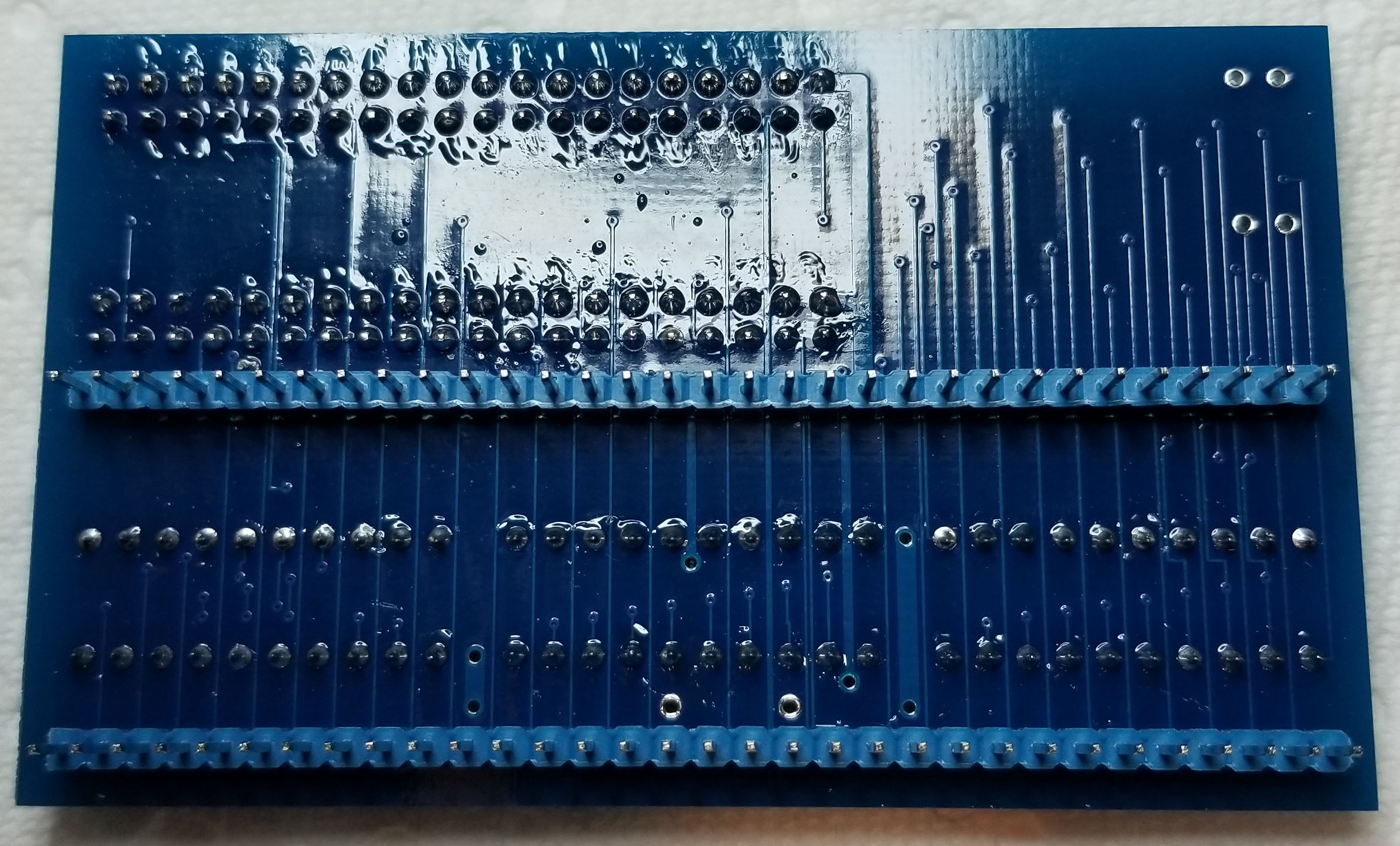
My other boards...
Let me know if you see any issues. These are prior to removing the flux from the boards and I need to install the resistors (which at this point I am assuming are the same as the Shield)
DIL40 Board Top & Bottom

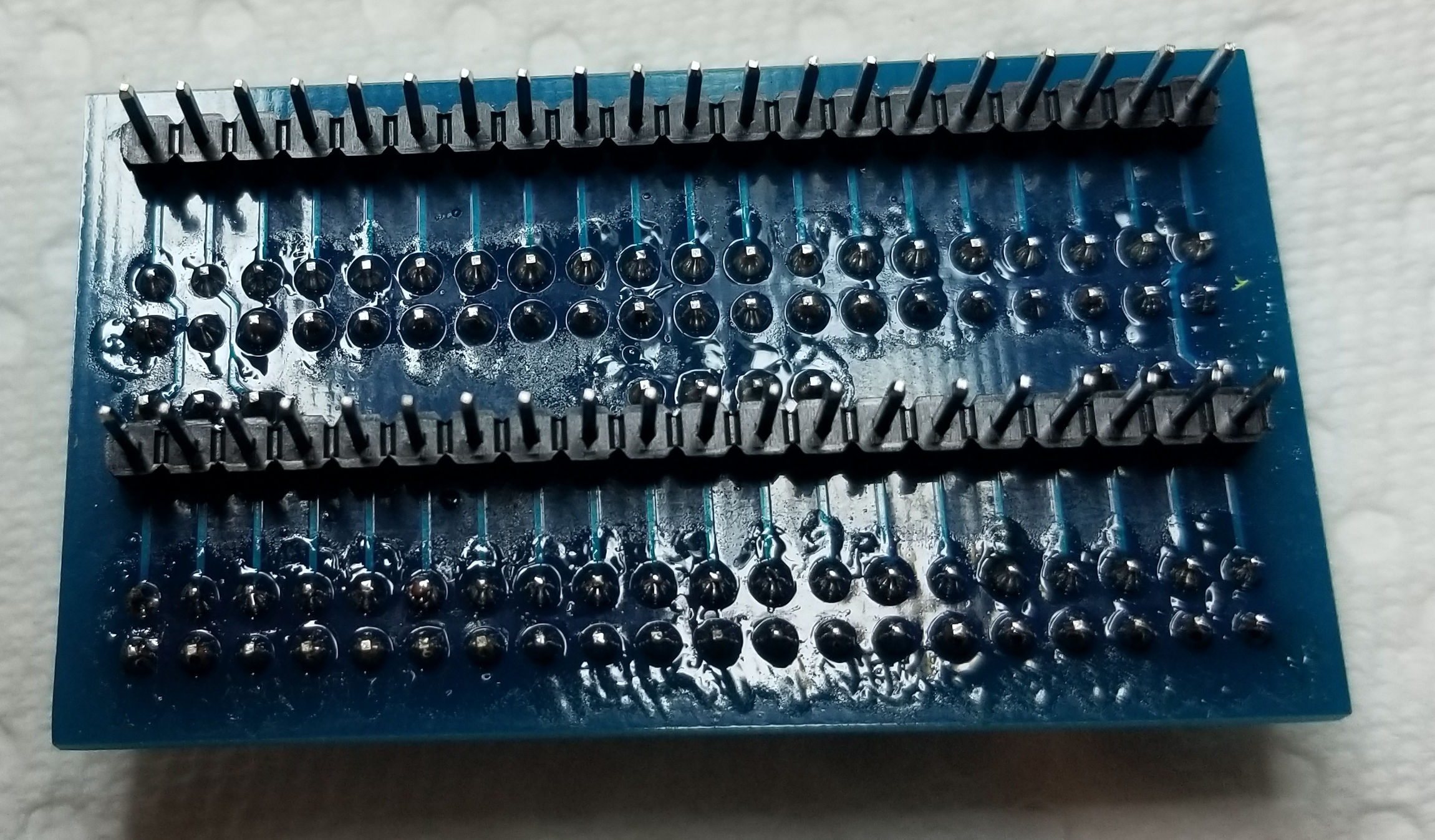
8080 Board Top & Bottom
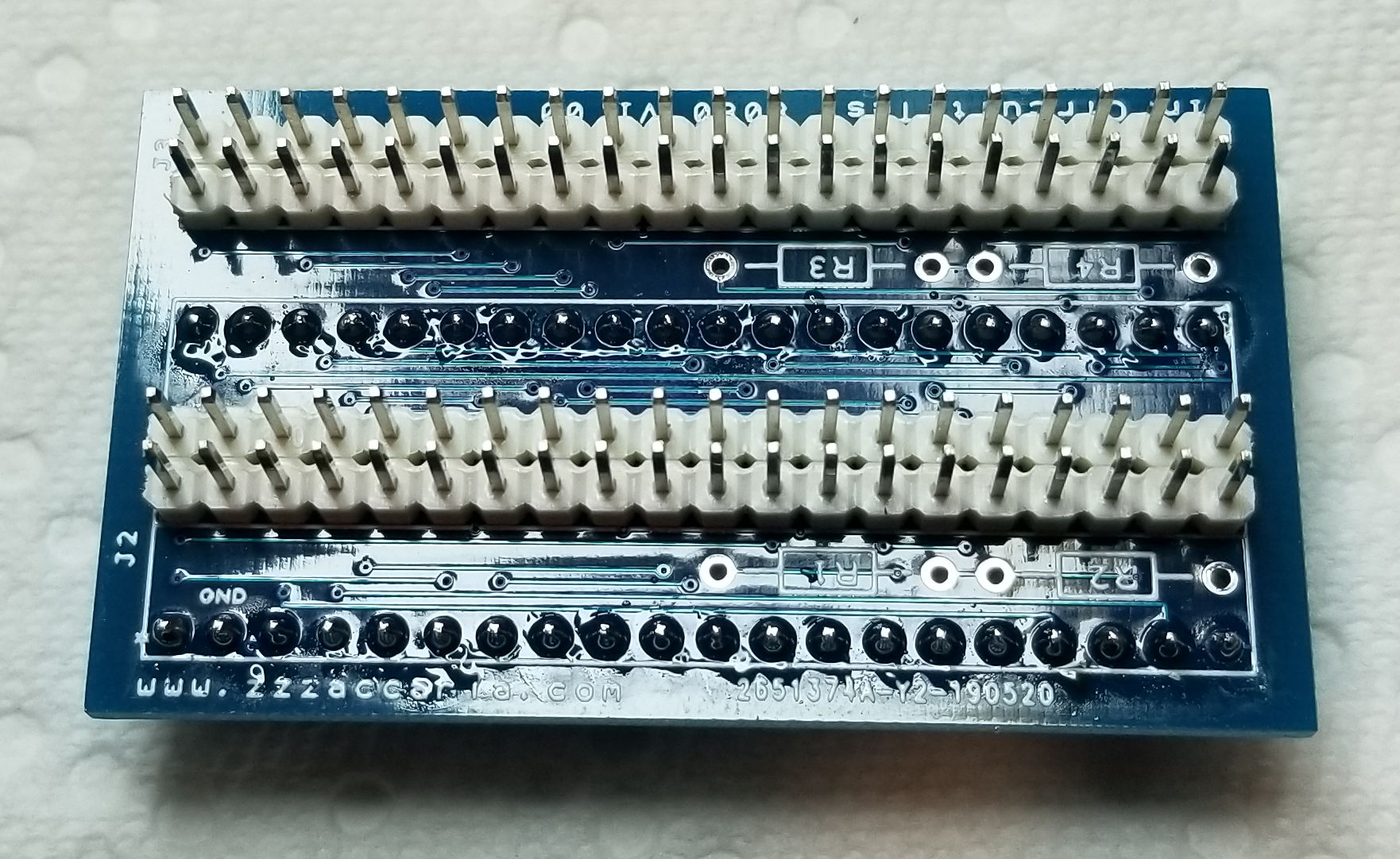
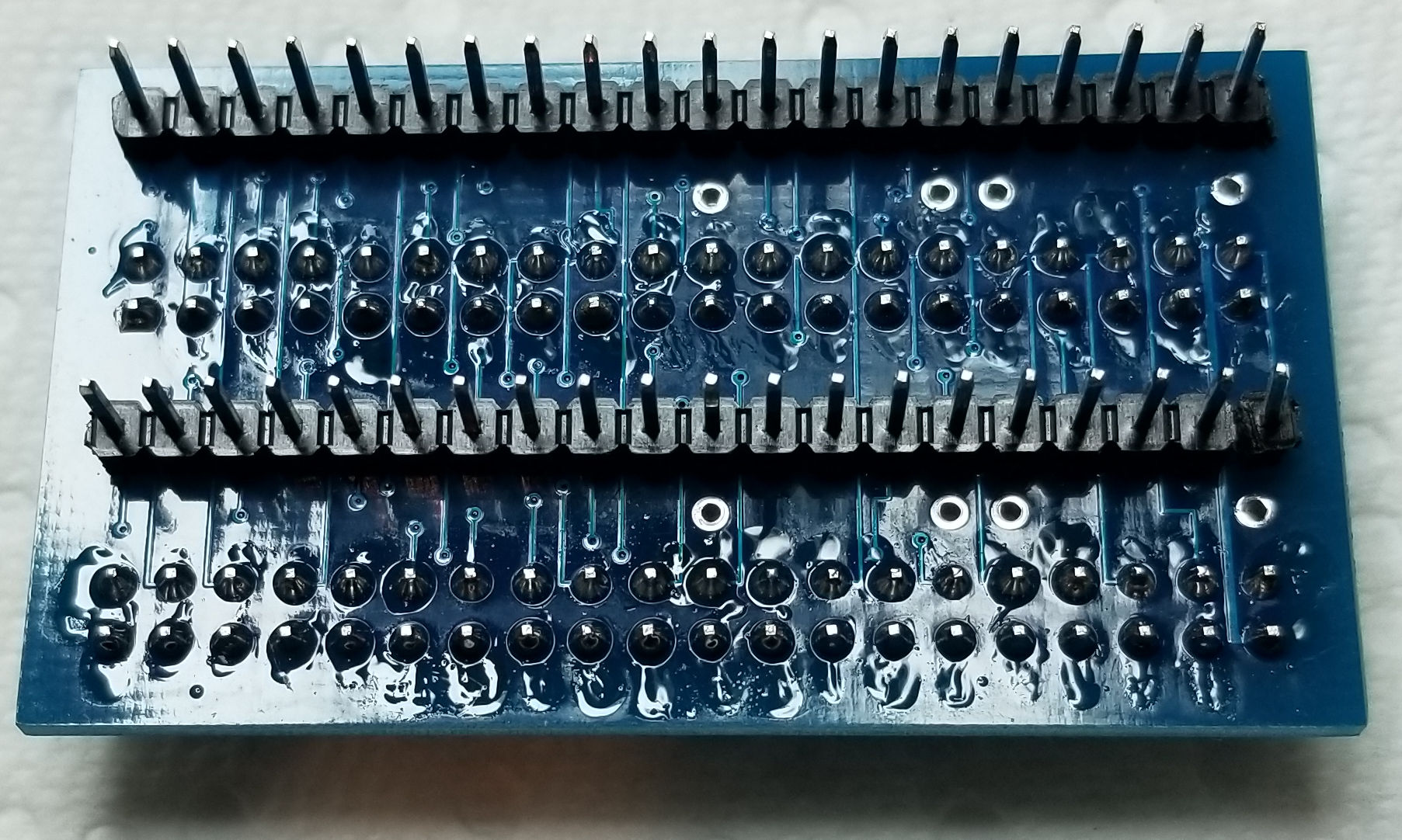
68000 Board Top & Bottom
Let me know if you see any issues. These are prior to removing the flux from the boards and I need to install the resistors (which at this point I am assuming are the same as the Shield)
DIL40 Board Top & Bottom
8080 Board Top & Bottom
68000 Board Top & Bottom
Finished building mine.
PROTIP:
Test on a known working board.I had problems using it with a scramble board I'm fixing.
Figured it was the CPU socket at fault-pin 40 was not connecting properly so was getting weird results.
Could someone on here help me figure out how to add games.
Would like to try putting choplifter on this but looking at the files I'm having difficulty figuring out how the memory settings relate to a memory map from mame.
Ok, some questions concerning the software side of things....
I've got my Windows App up and running (about 85% done with it). I've also written the Ardunio side of things that communicate with the App via USB.
I've been digging through Paul's code on the Arduino side.
I want to make it so that we are dealing with the CPU only and nothing game specific. The Windows App would drive the CPU features.
Starting with the 6502 implementation and was wondering:
1) Why does the Rom Size matter?
2) Seems to always do the Bus Check in the constructor, are there times you wouldn't do a bus check?
3) It seems that initializing the CPU is going to be game specific?
Ideally my goals are to say "Read Memory from X to Y", "Write X to Address Y".
I want all the CPU's in the Arduino and to send a command that tells it which CPU to use and then use generic methods to read and write to memory.
What other functions are useful as well?
Lurch666 said:Could someone on here help me figure out how to add games.
Would like to try putting choplifter on this
Yeah having a working board to compare to does really help especially when you are porting the ICT to a new game for the first time.
Adding new games is sort of missing from the manual... and I guess the manual itself is missing!! I had a lot of help from Paul when I added my first game so he explained quite a fair bit to me. If I have some time I'll port a new game (Snow Bros) and detail the steps I take so you can do the same with Choplifter. Then if any questions come up I can answer as we go.

It looks to me like the resistor footprint is an LR0204 form factor. Irem were fans of this resistor size.
Here is a Farnell Link for 1/4w 100ohm ones.
Here is a Farnell Link for 1/4w 100ohm ones.
Case is 99% complete. I am going to tweak the top cover a bit to fit a little nicer, but other than that it's pretty much done.
Once it's complete I'll post the STL files to Thingiverse and post a link to it here.
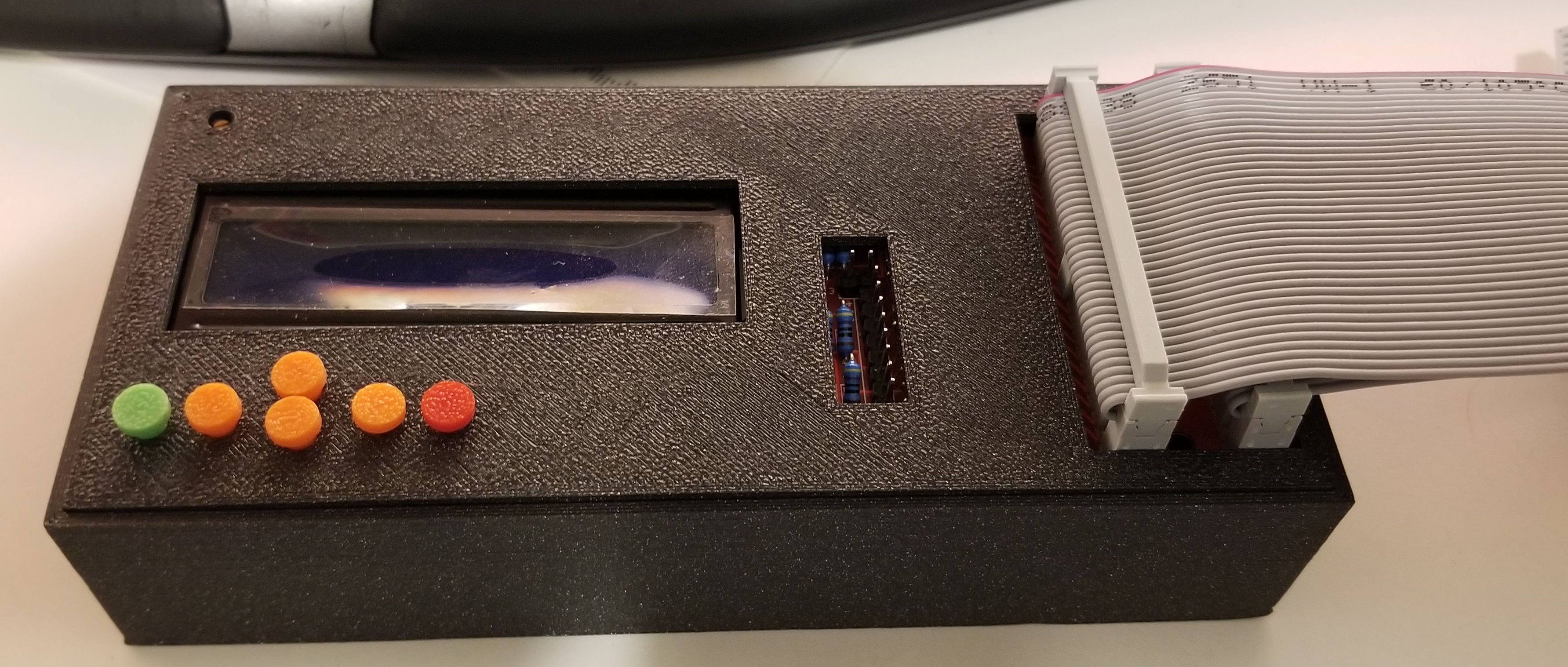
Once that's done I'll go back to working on the Generic Driver for the Arduino and finish up my windows app.
Once it's complete I'll post the STL files to Thingiverse and post a link to it here.
Once that's done I'll go back to working on the Generic Driver for the Arduino and finish up my windows app.
- Credits
- 763CR
Started on mine today, dear god I'm already sick of soldering headers.
Edit: Nope, I was wrong... doing resistors is EVEN MORE BORING than doing the headers. It's like replacing rom sockets on old Atari PCBS.....
yorkshire_spam2019-06-15 21:54:23
Edit: Nope, I was wrong... doing resistors is EVEN MORE BORING than doing the headers. It's like replacing rom sockets on old Atari PCBS.....
yorkshire_spam2019-06-15 21:54:23