
Yes I can help but do the basic checks first.I’m looking for someone to test and repair it, the game worked well for a few weeks before stopping , can you help ??

You are using an out of date browser. It may not display this or other websites correctly.
You should upgrade or use an alternative browser.
You should upgrade or use an alternative browser.
Galaxian 1980 repair
- Thread starter Jukev200
- Start date
You could really do with trying some simple checks first.
Are you getting a glow on the neck of the CRT when it's turned on?
Do you have a simple multi meter to check power to the PCB?
If no one can make it to yours I can check the PCB if you send it to me and cover the return postage but it would be a waste of money if the PCB is working.
Attachments
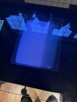
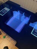
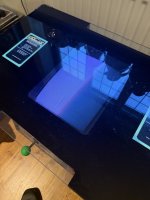
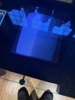

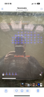
That looks like retrace lines on the monitor, did you adjust the screen pot up to get that or is that how it switches on now?.
That’s how it came on. I haven’t turned it on for a couple of weeks , wasn’t showing anything just recently. It has come up with a grid of numbers and letters when it first stopped working ?That looks like retrace lines on the monitor, did you adjust the screen pot up to get that or is that how it switches on now?.
That’s how it came on. I haven’t turned it on for a couple of weeks , wasn’t showing anything just recently. It has come up with a grid of numbers and letters when it first stopped working ?
Ok sounds like it was once booting if you say it had grid and numbers as that's how it boots but when it was working were those lines you see now still showing on the screen as that suggests the screen voltage is set too high on the flyback of the monitor but the game board has failed.
That looks like retrace lines on the monitor, did you adjust the screen pot up to get that or is that how it switches on now?.
Attachments

Ok sounds like it was once booting if you say it had grid and numbers as that's how it boots but when it was working were those lines you see now still showing on the screen as that suggests the screen voltage is set too high on the flyback of the monitor but the game board has failed.
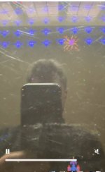
As Sukhbir suggest's there is definitely something going on with the pcb, if you look closely, over the far edge, the graphics look glitchy or corrupted slightly.
Looks like it was on it's way out back then and now has failed completely
Looks like it was on it's way out back then and now has failed completely
As Sukhbir suggest's there is definitely something going on with the pcb, if you look closely, over the far edge, the graphics look glitchy or corrupted slightly.
Looks like it was on it's way out back then and now has failed completely
Attachments
So you will have access to a multimeter that's a good start, so test the edge connector going to the board, here is the Galaxian pinout. Where it reads 'Volts AC', substitute that for 5v DC and 12v DC as your board looks like its been converted to run DC voltage.
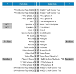
Ok, great , will have a look later today when I get home , thank you 👍So you will have access to a multimeter that's a good start, so test the edge connector going to the board, here is the Galaxian pinout. Where it reads 'Volts AC', substitute that for 5v DC and 12v DC as your board looks like its been converted to run DC voltage.
View attachment 48825
So you will have access to a multimeter that's a good start, so test the edge connector going to the board, here is the Galaxian pinout. Where it reads 'Volts AC', substitute that for 5v DC and 12v DC as your board looks like its been converted to run DC voltage.
View attachment 48825
Attachments
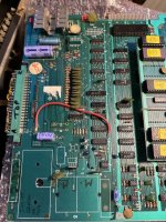
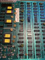
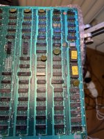
So you will have access to a multimeter that's a good start, so test the edge connector going to the board, here is the Galaxian pinout. Where it reads 'Volts AC', substitute that for 5v DC and 12v DC as your board looks like its been converted to run DC voltage.
View attachment 48825