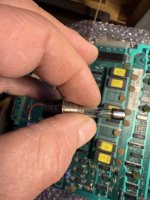
Black probe on Ground on the circuit board will do, A or 1 / Z or 22 for easy access then Red probe to C,D,3,4 = 5vdc and then W,X,18,19 = 12vdcHi , bit of a novice question , when trying to get the dc voltage reading I obviously touch on the various pin A to Z with one lead. Where do I ground the other lead, on the metal casing of the cabinet or somewhere on the circuit board ??
You are using an out of date browser. It may not display this or other websites correctly.
You should upgrade or use an alternative browser.
You should upgrade or use an alternative browser.
Galaxian 1980 repair
- Thread starter Jukev200
- Start date
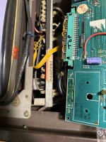
I personally don’t think you’ve got a power issue, but it is always good to check. Going from your updated information, I’d say the most likely problem is the chip sockets on your board. Try reseating every socketed chip (ie, turn the power off, carefully remove the chip using a small flat bladed screwdriver and re-insert the chip making sure you put it back in the same orientation as it was originally- take photos if necessary). The long rectangular daughter board might need reseating as well.
Don’t seem to be getting any readings ?Black probe on Ground on the circuit board will do, A or 1 / Z or 22 for easy access then Red probe to C,D,3,4 = 5vdc and then W,X,18,19 = 12vdc
This.I personally don’t think you’ve got a power issue, but it is always good to check. Going from your updated information, I’d say the most likely problem is the chip sockets on your board. Try reseating every socketed chip (ie, turn the power off, carefully remove the chip using a small flat bladed screwdriver and re-insert the chip making sure you put it back in the same orientation as it was originally- take photos if necessary). The long rectangular daughter board might need reseating as well.
Yet a garbage screen indicates otherwise - is the meter set to AC? Being used to measuring domestic stuff, it's possible.If he's correctly measuring voltages on the board and getting nothing, there's obviously a power issue somewhere along the line. Lol
Or DC, and the DC converted board is being pumped with AC?...shudder! Although this would be impossible.
I understood that screenshot was an old one taken before it completely died.Yet a garbage screen indicates otherwise - is the meter set to AC? Being used to measuring domestic stuff, it's possible.
Or DC, and the DC converted board is being pumped with AC?...shudder! Although this would be impossible.
Ah, time to trace the power from source!I understood that screenshot was an old one taken before it completely died.
The screen lights purple grey and flickers at the momentI understood that screenshot was an old one taken before it completely died.
I understood that screenshot was an old one taken before it completely died.

I clipped one lead on A and touched the other lead with probe on the pins as indicated early, meter not showing a reading. I put it across a C type battery to check meter and read 2v dcYet a garbage screen indicates otherwise - is the meter set to AC? Being used to measuring domestic stuff, it's possible.
Or DC, and the DC converted board is being pumped with AC?...shudder! Although this would be impossible.
Did this, no differenceThis.

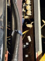
You really need to start unclipping some of those wires and tracing back from the edge connecter to see what wire leads where. That yellow ribbon cable of 6 wires looks mainly for video so you can ignore that bunch of wiring.
It doesn't help having the +12v in yellow on 'X' pin connector with a bunch of other yellow wires. The off-white wire on the 4th pin up from 'A', letter 'D' you need to trace where that wire goes for +5v so start with that first and that will lead you to your power source for the board.
It doesn't help having the +12v in yellow on 'X' pin connector with a bunch of other yellow wires. The off-white wire on the 4th pin up from 'A', letter 'D' you need to trace where that wire goes for +5v so start with that first and that will lead you to your power source for the board.
Last edited: