Ok, thanks, will have a look in the daylight tomorrow and report back, thanks for all the help so far 👍👍You really need to start unclipping some of those wires and tracing back from the edge connecter to see what wire leads where. That yellow ribbon cable of 6 wires looks mainly for controls so you can ignore that bunch of wiring.
It doesn't help having the +12v in yellow on 'X' pin connector with a bunch of other yellow wires. The off-white wire on the 4th pin up from 'A', letter 'D' you need to trace where that wire goes for +5v so start with that first and that will lead you to your power source for the board.

You are using an out of date browser. It may not display this or other websites correctly.
You should upgrade or use an alternative browser.
You should upgrade or use an alternative browser.
Galaxian 1980 repair
- Thread starter Jukev200
- Start date
Ok, thanks, will have a look in the daylight tomorrow and report back, thanks for all the help so far 👍👍
Attachments


If it goes to that board then likely all the supply voltages are generated from there back the board, a bit like an older version of a switching power supply.
This is what you would buy today for a replacement (New switching power supply)

Did you do a continuity test from that pin to the game board to confirm it was definitely going to that plug or did you manually trace it by eye?.
What does the voltage measure from the off-white pin?
Also I can see the green and yellow wires are both attached to 'X' pin on the edge connector so that would make that it +12v so try to see also what the green and yellow wires from the plug are measuring, do a continuity check from the plug to the edge connector for both, especially the yellow wire as there are quite a few yellow wires off that edge connector, even tracing manually by eye it's very easy to follow the wrong wire.
The additional +5v wire on the game board that's soldered looks like its ripped up the copper plating off the board so not sure how effective that is, can you just check that, it may be the picture angle.

This is what you would buy today for a replacement (New switching power supply)
Did you do a continuity test from that pin to the game board to confirm it was definitely going to that plug or did you manually trace it by eye?.
What does the voltage measure from the off-white pin?
Also I can see the green and yellow wires are both attached to 'X' pin on the edge connector so that would make that it +12v so try to see also what the green and yellow wires from the plug are measuring, do a continuity check from the plug to the edge connector for both, especially the yellow wire as there are quite a few yellow wires off that edge connector, even tracing manually by eye it's very easy to follow the wrong wire.
The additional +5v wire on the game board that's soldered looks like its ripped up the copper plating off the board so not sure how effective that is, can you just check that, it may be the picture angle.
Last edited:
I’veIf it goes to that board then likely all the supply voltages are generated from there back the board, a bit like an older version of a switching power supply.
This is what you would buy today for a replacement (New switching power supply)
View attachment 48903
Did you do a continuity test from that pin to the game board to confirm it was definitely going to that plug or did you manually trace it by eye?.
What does the voltage measure from the off-white pin?
Also I can see the green and yellow wires are both attached to 'X' pin on the edge connector so that would make that it +12v so try to see also what the green and yellow wires from the plug are measuring, do a continuity check from the plug to the edge connector for both, especially the yellow wire as there are quite a few yellow wires off that edge connector, even tracing manually by eye it's very easy to follow the wrong wire.
The additional +5v wire on the game board that's soldered looks like its ripped up the copper plating off the board so not sure how effective that is, can you just check that, it may be the picture angle.
View attachment 48904
I’ve just checked continuity, off white lead measure .35 ohmsIf it goes to that board then likely all the supply voltages are generated from there back the board, a bit like an older version of a switching power supply.
This is what you would buy today for a replacement (New switching power supply)
View attachment 48903
Did you do a continuity test from that pin to the game board to confirm it was definitely going to that plug or did you manually trace it by eye?.
What does the voltage measure from the off-white pin?
Also I can see the green and yellow wires are both attached to 'X' pin on the edge connector so that would make that it +12v so try to see also what the green and yellow wires from the plug are measuring, do a continuity check from the plug to the edge connector for both, especially the yellow wire as there are quite a few yellow wires off that edge connector, even tracing manually by eye it's very easy to follow the wrong wire.
The additional +5v wire on the game board that's soldered looks like its ripped up the copper plating off the board so not sure how effective that is, can you just check that, it may be the picture angle.
View attachment 48904

It’s not ripped , just a big dollop of solder
Attachments


If you put meter on diode test and beep out the off-white, green and red wires from the black connector back to the board, all we are doing for now is making sure you are selecting the correct wires to check for dc voltages then if you are getting the correct voltage at the connector and not back to the board then it is a break in the wire to the board.
If no voltage at the power supply then the power supply requires fixing or replacing for a more modern equivalent like the one I posted. The one you have could probably be fixed but for relaibilty you're probably best replacing it because there will probably be another component die in the near future due to its age.
It may be easier for me to pop round to show you all the stuff to test, these machines take a bit of maintenance to keep them running due to their age and failing components but with a little guidance you will be able to do some simple checks when something goes wrong again.
The edge connector and wiring in general needs a bit of a tidy up to make it more reliable, espcially if all you want to be able to do is plug it in and work all the time.
If no voltage at the power supply then the power supply requires fixing or replacing for a more modern equivalent like the one I posted. The one you have could probably be fixed but for relaibilty you're probably best replacing it because there will probably be another component die in the near future due to its age.
It may be easier for me to pop round to show you all the stuff to test, these machines take a bit of maintenance to keep them running due to their age and failing components but with a little guidance you will be able to do some simple checks when something goes wrong again.
The edge connector and wiring in general needs a bit of a tidy up to make it more reliable, espcially if all you want to be able to do is plug it in and work all the time.
Ok, that sounds great , I’m in Sevenoaks , Kent ??If you put meter on diode test and beep out the off-white, green and red wires from the black connector back to the board, all we are doing for now is making sure you are selecting the correct wires to check for dc voltages then if you are getting the correct voltage at the connector and not back to the board then it is a break in the wire to the board.
If no voltage at the power supply then the power supply requires fixing or replacing for a more modern equivalent like the one I posted. The one you have could probably be fixed but for relaibilty you're probably best replacing it because there will probably be another component die in the near future due to its age.
It may be easier for me to pop round to show you all the stuff to test, these machines take a bit of maintenance to keep them running due to their age and failing components but with a little guidance you will be able to do some simple checks when something goes wrong again.
The edge connector and wiring in general needs a bit of a tidy up to make it more reliable, espcially if all you want to be able to do is plug it in and work all the time.
Just a follow up on this, I went to see Steve over the course of 3 weekends and fixed the Galaxian board and machine in general, turned out to be dodgy sockets for the rom satellite board and I think the +5v and GND on the badly wired fingerboard had shorted out as there was no power coming from the original Nintendo PCB power supply. The pin connections were very loose in the connector and there was a lot of movement between adjacent pins and I think they must have came into contact with each other.
I replaced all the flaky sockets and performed Macro's single ram and Galaxian/Super Galaxian rom mod on his board so he can now select between the 2 Galaxian games via a little switch on a new daughter board I made for him.
The cab was completely rewired from scratch, I also wired up the coin mech, service and test switches which either had cut wires or previously non functional.
The monitor looked to be completely shot, the screen voltage looked way too high with retrace lines and I was unable to turn it down using the screen pot so I dropped in a replacement 13" monitor for him with a view to looking at the old monitor at another time to try to fix it as a spare for him.
Steve was a really nice, all round friendly guy, it was a pleasure helping him get his machine back up and running again. He did send me a video of his grandson happily playing it which also included a nice little thank you message which I thought was very touching.
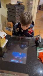
I hope Steve doesn't mind me sharing but below is a screenshot from the video showing his grandson playing the game on Christmas Day.
I replaced all the flaky sockets and performed Macro's single ram and Galaxian/Super Galaxian rom mod on his board so he can now select between the 2 Galaxian games via a little switch on a new daughter board I made for him.
The cab was completely rewired from scratch, I also wired up the coin mech, service and test switches which either had cut wires or previously non functional.
The monitor looked to be completely shot, the screen voltage looked way too high with retrace lines and I was unable to turn it down using the screen pot so I dropped in a replacement 13" monitor for him with a view to looking at the old monitor at another time to try to fix it as a spare for him.
Steve was a really nice, all round friendly guy, it was a pleasure helping him get his machine back up and running again. He did send me a video of his grandson happily playing it which also included a nice little thank you message which I thought was very touching.
I hope Steve doesn't mind me sharing but below is a screenshot from the video showing his grandson playing the game on Christmas Day.
Last edited:


Thank you Craig, you worked a miracle to get it up and running for Christmas Day !! Craig was brilliant, very knowledgable in all aspects of the repair, which needs a wide skill set to go through everything properly. I really appreciate all the effort and I’m sure my brother would be pleased to see it up and running so well, god bless him. Everyone at Christmas enjoyed playing it, which just goes to show what great games they were when designed in the late 70’s, Sam the 9 year old grandson especially enjoyed it , thanks again Craig 👍👍👍Just a follow up on this, I went to see Steve over the course of 3 weekends and fixed the Galaxian board and machine in general, turned out to be dodgy sockets for the rom satellite board and I think the +5v and GND on the badly wired fingerboard had shorted out as there was no power coming from the original Nintendo PCB power supply. The pin connections were very loose in the connector and there was a lot of movement between adjacent pins and I think they must have came into contact with each other.
I replaced all the falky sockets and performed Macro's single ram and Galaxian/Super Galaxian rom mod on his board so he can now select between the 2 Galaxian games via a little switch on a new daughter board I made for him.
The cab was completely rewired from scratch, I also wired up the coin mech, service and test switches which either had cut wires or previously non functional.
The monitor looked to be complete shot, the screen voltage looked way too high with retrace lines and I was unable to turn it down using the screen pot so I dropped in a replacement 13" monitor for him with a view to looking at the monitor at another time to try to fix it as a spare for him.
Steve was a really nice, all round friendly guy, it was a pleasure helping him get his machine back up and running again. He did send me a video of his grandson happily playing it which also included a nice little thank you message which I thought was very touching.
I hope Steve doesn't mind me sharing but below is a screenshot from the video showing his grandson playing the game on Christmas Day.
View attachment 50322
Forgot to mention... when I rewired it, I rewired it to Jamma so Steve can now utilise his machine to play other vertical Jamma arcade boards or maybe a Mister setup.
The power supply was also replaced for a more modern replacement, I made up a little digital 5v and 12v display add on board so Steve can check on the power voltages.
The power supply was also replaced for a more modern replacement, I made up a little digital 5v and 12v display add on board so Steve can check on the power voltages.