You are using an out of date browser. It may not display this or other websites correctly.
You should upgrade or use an alternative browser.
You should upgrade or use an alternative browser.
Midway Space Invaders Motherboard
- Thread starter funhouse
- Start date
Dammit.
Was sure that was the solution.
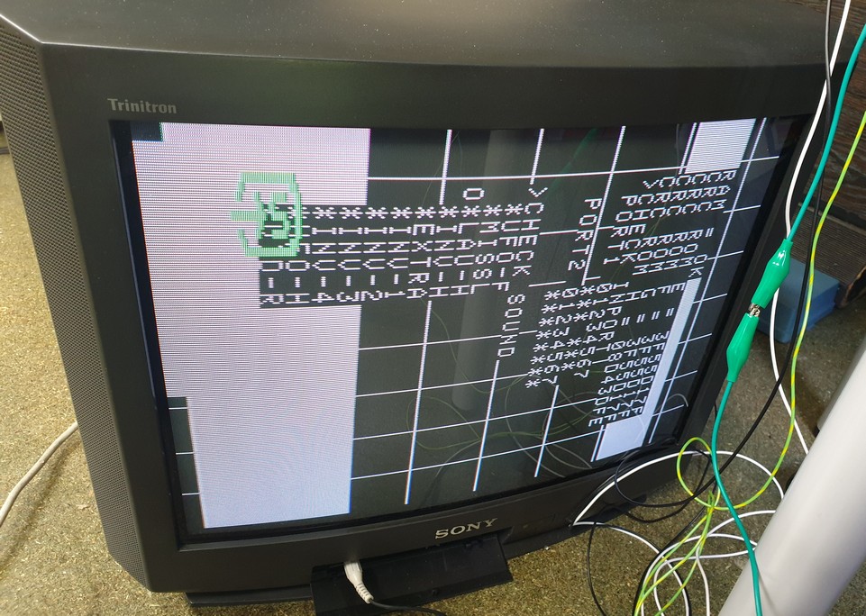
Well I doubt exactly half of your ram is faulty so it's puzzling how it looks like it is unless I'm misunderstanding the output from the test.
1-8 is one bank of ram and A-H is the other bank.
I'm presuming the first A is just off screen.
I presume you meant pins 2 and 7 instead of 1 and 7.
Lurch6662019-05-23 17:06:58
Was sure that was the solution.
Well I doubt exactly half of your ram is faulty so it's puzzling how it looks like it is unless I'm misunderstanding the output from the test.
1-8 is one bank of ram and A-H is the other bank.
I'm presuming the first A is just off screen.
I presume you meant pins 2 and 7 instead of 1 and 7.
Lurch6662019-05-23 17:06:58
Sorry, yes pin 2 I'm 99.9% sure.
Yes the A could be off screen - I also wondered why the E and F are close to each other?
While waiting for the Eprom I put the 8080 in and followed the Midway Test Procedure:
http://antelopearcade.com/files/Miscellaneous/MIDWAY_8080_TEST.pdf
I got to page 13 where you test the Multiplexers IC74153's at A2 B2 C2 and D2
I got pulses on pins 7 and 9 for all of them. I then grounded pins 4 and 12 on each chip (one chip at a time so only two grounds rather than 8 grounds at once).
IC A2 didn't do what it was supposed to but I'm still not sure if that was because I didn't ground 8 pins at once. I put another 74153 on top of its legs as a quick check but no change.
funhouse2019-05-23 17:13:22
Interesting. Looking closely at it C5 I see it is the only ceramic chip on the board. The solder looks original though.
There is no short between pins 2 and 7 with a multimeter. But on a 'scope the outputs on the two pins are identical. Are they supposed to be different?
There is no short between pins 2 and 7 with a multimeter. But on a 'scope the outputs on the two pins are identical. Are they supposed to be different?
OK.
Ram A-H is in positions H8 (A) to H15 (H).
You mention you have replaced some ram.
If one of the rams is in one of these positions try replacing it with the other ram you replaced and see if you get a different message.
What I'm trying to do is see if you have a ram addressing problem or just a ram problem.
If you can get the test where it doesn't show all chips from A to H as faulty you know the addressing is working.
Or could be just that all that ram IS faulty and it's just a coincidence.
Lurch6662019-05-23 20:58:35
Just tested C5 pins 2 and 7 with two probes. It looks like they are out of phase and of similar signal but slightly different amplitudes.
I have already newly socketed 2 RAMs in H and 2 RAMs in G. I swapped across and also from some other RAM I had but the same picture is shown. So I guess it's the addressing (or I am terribly unlucky with the RAM).
Is there a way to test the RAM out of circuit?
I have already newly socketed 2 RAMs in H and 2 RAMs in G. I swapped across and also from some other RAM I had but the same picture is shown. So I guess it's the addressing (or I am terribly unlucky with the RAM).
Is there a way to test the RAM out of circuit?
Wow !
My son asked me to show him the board and we both used the probes on it. He shorted pins 15 and 16 on A2 and it started working!
A2 was the last test I did in the Standardized test and as I said earlier I wasn't sure about it. Looks like either the short restarted the chip or there was some dry solder joints. Will resolder but we are getting there!
Cheers all for the assistance!

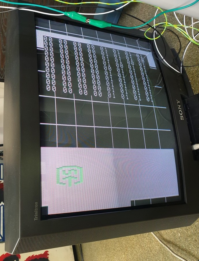
The second screen means that either half the sifters are faulty or the 74LS174s at C5 or D5 on the soundboard are failing.
Hope it's the 174 chips as apparently 25S10 are near impossible to get.
Unless you are lucky and the daughterboard is using other chips for shifting.
Is it working consistently now or do you have to sort the pins everytime?
The ports are the inputs for the game (left,right fire etc)
Hope it's the 174 chips as apparently 25S10 are near impossible to get.
Unless you are lucky and the daughterboard is using other chips for shifting.
Is it working consistently now or do you have to sort the pins everytime?
The ports are the inputs for the game (left,right fire etc)
It gets to the test each time now with same result as above. Put the Braze in and it gives:
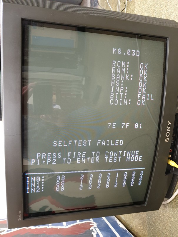
It lets me play though and the graphics have some problems but it is working!!
I can't seem to adjust the volume though (I take it is the pot. on the daughterboard? - mine just turns to no effect).
Putting them back in I see at least one of the original PROMs has a different CRC too.
The Daughterboard is using the 25S10s

funhouse2019-05-24 16:43:49
It lets me play though and the graphics have some problems but it is working!!
I can't seem to adjust the volume though (I take it is the pot. on the daughterboard? - mine just turns to no effect).
Putting them back in I see at least one of the original PROMs has a different CRC too.
The Daughterboard is using the 25S10s
funhouse2019-05-24 16:43:49
Thanks Lurch666. Will have a look this weekend to see if I can get either off some junk boards I bought.
Coming to think about this. We can buy cheap IC testers on Ebay that will test all common logic chips, but is there such a thing as an IC emulator?
It would be great to piggyback or plug-in an IC emulator in this sort of situation.
Coming to think about this. We can buy cheap IC testers on Ebay that will test all common logic chips, but is there such a thing as an IC emulator?
It would be great to piggyback or plug-in an IC emulator in this sort of situation.