Midway Space Invaders Motherboard

Lurch666

Active member
Feedback
21 (100%)
Credits
4,142CR
Well since you have the base explosion the noise circuit should be ok.

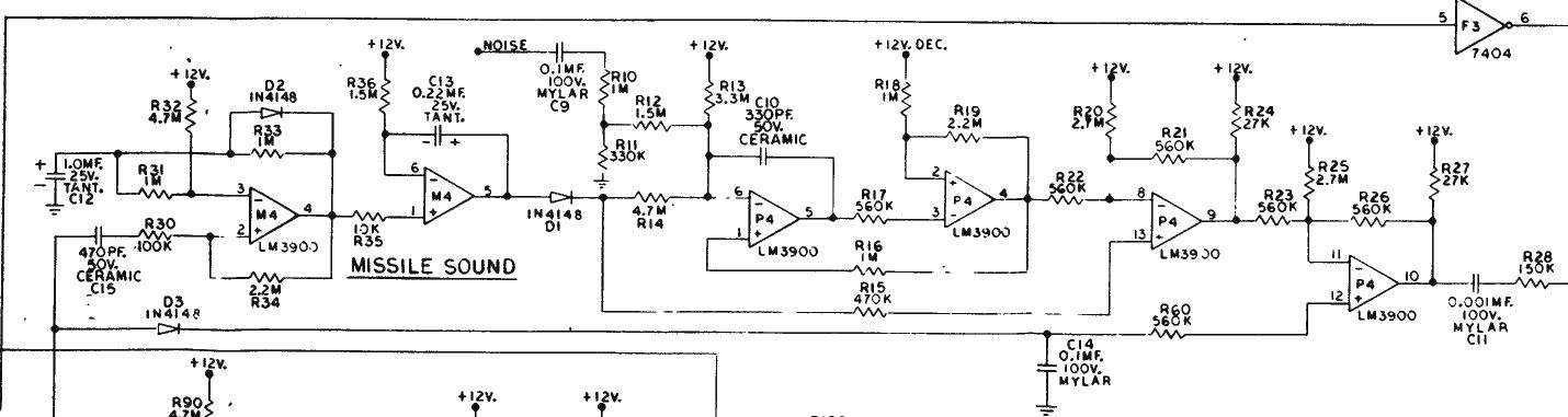
Looking at the schematics check that M4 is getting 12v since you have replaced it but it's common to both your missing sounds.

If I get a chance I'll dig out my cosmic invaders and see if I can find out which amp is equivalent to M4 on my board and check to see if I can see anything on pin 2

EDIT:took a bit of tracking but managed to figure out which chip is M4 on my cosmic invader board and my scope shows a quick +1V deflection on pin 2 when firing.

Lurch6662019-06-18 16:19:20
 

funhouse

Active member
vacBacker
Feedback
3 (100%)
Credits
360CR
All the LM3900s are getting 12V at VCC pin 14. The diodes in the area seem okay. I haven't changed any capacitors on this board.

I took two photos, normal and heat:

SIdaughterLM3900noheat.jpg


SIdaughterLM3900heat.jpg


The K LM3900s are hot and sure enough the Explosion circuit works.

P4 looks warm but M4 isn't (even though it's new) and that Missile circuit doesn't work.

To add - although the capacitors at the top look very hot - when you look at the whole board you can see that quite a few of the components above are that hot.

Edit. Just read your edit Lurch. I was only using a logic probe so wouldn't have seen 1v I guess. Will try with the oscilloscope next.

funhouse2019-06-19 16:57:57
 

funhouse

Active member
vacBacker
Feedback
3 (100%)
Credits
360CR
Used an oscilloscope on M4 pin 2 and there is the tiniest of spikes only.

So I followed F4 pin 10 (which is good) along and get to the 470pf 50V ceramic C15 and nothing gets past it. I put a capacitor tester across it and nothing - it's open circuit.

No time to replace it now but progress I hope!
 

funhouse

Active member
vacBacker
Feedback
3 (100%)
Credits
360CR
Well my tester couldn't go that low to 470pf. I tried a different tester I had and a multimeter and it looks okay.

I then thought to try the 12V inputs as you suggested Lurch666.

M4 pin 3 = 11.3V

M4 pin 6 = 11.7V

P4 pin 6 = 0.1V ???

P4 pin 2 = 0.6V ???

P4 pin 8 = 0.6V ???

P4 pin 11 = 11.17V

So it looks like one 12V and one 12V Dec. (what does Dec. mean?) are bad. As yet I don't know where they get supplied from.

missilecircuit.jpg


funhouse2019-06-19 21:15:13
 

Lurch666

Active member
Feedback
21 (100%)
Credits
4,142CR
Look on the right of the schematic just below the noise generator. That gives the part that generates +12V dec.

+12V dec is also used in the explosion sound circuit so it should be ok but maybe not making it to the missile sound?
 

funhouse

Active member
vacBacker
Feedback
3 (100%)
Credits
360CR
Checked and 12V seems to be coming in at all those okay.

I'm 100% sure it used to work but I now notice that the base explosion doesn't sound anymore. That points to the noise generator 4006 and 4030 doesn't it - I've checked all the resistors and diodes around it. Will order those two next.
 

funhouse

Active member
vacBacker
Feedback
3 (100%)
Credits
360CR
This board is trying to cause me (and you) problems!!
smiley5.gif


No, not yet but I refuse to give-in!

The Invader Hit looks like it has the 4006 in the circuit so I'm hoping it's that.

funhouse2019-06-20 16:27:11
 

RaveN

Active member
vacBacker
Feedback
1 (100%)
Credits
1,325CR
The 4006 is usually fairly robust. The 4030 does fail, but usually results in a "fart" sound for the explosion.

Measuring DC in the audio signal path in this area isn't typically reliable, as the diodes will block DC.

Whenever working on these boards, it's common to just replace all LM3900s. They're still available and cost about 40p each, so they're often replaced regardless.
 
Top