
You are using an out of date browser. It may not display this or other websites correctly.
You should upgrade or use an alternative browser.
You should upgrade or use an alternative browser.
Missile Command Help
- Thread starter Purity
- Start date


Looks like the AR board has already been subjected to some pretty poor repair work. -5 was probably a problem before, hence 7905 previously replaced. Just desolder it. Then drop it back in so hole lines up with hole on heatsink. Should then be screwed in placed. Soldered in place. Legs trimmed to fit. That said, may not even be the 7905 that's at fault .... Worth checking schems for what else is in the -5 circuit. Not much is my guess.
tb lilley said:Looks like the AR board has already been subjected to some pretty poor repair work. -5 was probably a problem before, hence 7905 previously replaced. Just desolder it. Then drop it back in so hole lines up with hole on heatsink. Should then be screwed in placed. Soldered in place. Legs trimmed to fit. That said, may not even be the 7905 that's at fault .... Worth checking schems for what else is in the -5 circuit. Not much is my guess.
I think you are right. That 7905 has been replaced really badly.
To be on the safe side, I'll desolder it, and fit a brand new 7905 with a replacement MICA and use the plastic screw on the right to mount it to the heatsink, with some termal paste between the heatsink/MICA/voltage regulator
Can anyone confirm that it is ok to screw the LM305 directly to the heatsink with no MICA and a metal screw?
I found an image here, with both the 7905 and LM305 attached with a plastic screw and cable tie, so they will use an insulator. I'll do something similar when the new 7905 is fitted and in the correct position:
http://www.arcadesolution.com/35435_02.html
http://www.arcadesolution.com/35435_02.html
tb lilley said:Looks like the AR board has already been subjected to some pretty poor repair work. -5 was probably a problem before, hence 7905 previously replaced. Just desolder it. Then drop it back in so hole lines up with hole on heatsink. Should then be screwed in placed. Soldered in place. Legs trimmed to fit. That said, may not even be the 7905 that's at fault .... Worth checking schems for what else is in the -5 circuit. Not much is my guess.
If I am reading the schemes correctly I can only see the following on the -5 circuit:
22uf axial lead 35v Cap @ C24, C31
2.7 Ohm 1w Resistor @ R5
5.6k 1/4 W Resistor @ R33
3300uf axial lead 35v CAP C19 or C18?
CR8? 50v 2.5A Mini Axial-lead high current rectifier
Purity2013-11-01 19:18:01
I am totally stuck now.
Caps at C24, and 31 look ok on an ESR meter
Caps at C18 and C19 look ok on an ESR meter
I've measured CR8, CR7, CR6, CR5 as diodes and they are all roughtly the same values 900 odd
I measured R33 using the 20k Ohms setting on the multimeter, and it measures around 5.3 ish
Not measured R5 yet
Can't find anything wrong

Purity2013-11-01 20:36:17
Caps at C24, and 31 look ok on an ESR meter
Caps at C18 and C19 look ok on an ESR meter
I've measured CR8, CR7, CR6, CR5 as diodes and they are all roughtly the same values 900 odd
I measured R33 using the 20k Ohms setting on the multimeter, and it measures around 5.3 ish
Not measured R5 yet
Can't find anything wrong
Purity2013-11-01 20:36:17
A bit high.
Diodes CR5-CR8 rectify the AC voltage to DC, both neg and pos voltages. Off one pair of the diodes you'll (eventually) get the +22 and +12. Off the other pair -22 and -5.
Dunno. If everything else checks out I'd start to look at the 4 rectifying diodes. Have they been previously replaced? Are they the correct diodes as per schems? Not sure, but as the -22 is also high it might make sense to look at the diodes. Should be 4 x IN5401.
Edit: sorry to ask, but when you checked the diodes did you lift a leg on each?tb lilley2013-11-01 21:02:41
Diodes CR5-CR8 rectify the AC voltage to DC, both neg and pos voltages. Off one pair of the diodes you'll (eventually) get the +22 and +12. Off the other pair -22 and -5.
Dunno. If everything else checks out I'd start to look at the 4 rectifying diodes. Have they been previously replaced? Are they the correct diodes as per schems? Not sure, but as the -22 is also high it might make sense to look at the diodes. Should be 4 x IN5401.
Edit: sorry to ask, but when you checked the diodes did you lift a leg on each?tb lilley2013-11-01 21:02:41
Thanks for your help James.
As far as I can tell the diodes are the original diodes on the ARII.
No, I didn't left a leg to read them. I realise I should have done this, and it was a schoolboy error
I'll lift a leg on all of them tomorrow and check them again
Purity2013-11-01 22:17:29
As far as I can tell the diodes are the original diodes on the ARII.
No, I didn't left a leg to read them. I realise I should have done this, and it was a schoolboy error
I'll lift a leg on all of them tomorrow and check them again
Purity2013-11-01 22:17:29

I started to have a look at the PCB this morning. Found some interesting things, which may explain what I'm seeing? Hopefully you guys can comment. The PCB looks like it is an 04 = 6 roms, according to the manual.
I carefully lifted the ROM at H1 (35820-02). Pin 24 looks like it has a broken leg. Half of the leg looks like it is still in the socket. I suspect that this has been broken for a while
I checked the following roms against Missile Command (rev 3) mame rom. I could not find an 04 set
L/N1 - idents
N-P1 - idents
R1 - idents
H1 - broken leg, couldn't check
J/K1 - idents
L6 PROM - idents
Now this is the weird thing. ROM K/L1 does not ident?? It idents in Mame as Rev2. When I checked it againt a Rev2 rom it doesn't ident ??
I carefully lifted the ROM at H1 (35820-02). Pin 24 looks like it has a broken leg. Half of the leg looks like it is still in the socket. I suspect that this has been broken for a while
I checked the following roms against Missile Command (rev 3) mame rom. I could not find an 04 set
L/N1 - idents
N-P1 - idents
R1 - idents
H1 - broken leg, couldn't check
J/K1 - idents
L6 PROM - idents
Now this is the weird thing. ROM K/L1 does not ident?? It idents in Mame as Rev2. When I checked it againt a Rev2 rom it doesn't ident ??
Four MC board revision. -01 and -02 use ver 1 ROMs. -03 and -04 use ver 2 ROMs.
Ver 3 ROMs never made it out the factory door. Weren't known to exist until about 2 years ago. A guy in the US discovered V3 ROMs in a cab he acquired from the Atari engineering labs. They were dumped shortly after. Fixes 2 well known bugs (810k bonus city awards, and the screen 256 bug). I know this because I burnt the ROMs and did the tests. There's a thread on KLOV somewhere.
Anyway, you need to ident against ver 2 ROMS.
Edit: when I say I burnt the ROMs, it's just the one ROM that has changed code from the others. Can't remember off hand but likely K/L1. So everything else would check out against v3. tb lilley2013-11-17 14:05:18
Ver 3 ROMs never made it out the factory door. Weren't known to exist until about 2 years ago. A guy in the US discovered V3 ROMs in a cab he acquired from the Atari engineering labs. They were dumped shortly after. Fixes 2 well known bugs (810k bonus city awards, and the screen 256 bug). I know this because I burnt the ROMs and did the tests. There's a thread on KLOV somewhere.
Anyway, you need to ident against ver 2 ROMS.
Edit: when I say I burnt the ROMs, it's just the one ROM that has changed code from the others. Can't remember off hand but likely K/L1. So everything else would check out against v3. tb lilley2013-11-17 14:05:18
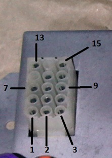
So back to the power issue. I took some readings out the AC/DC power block on the brick.
I don't have any schematics for the cocktail so used a combination of the sitdown/cabaret schemes
Anyway....
Pin 1 and 4 = 13.8v DC (expect 10.3v DC) acceptable
Pin 2 and 4 = 13.9v DC acceptable
Pin 3 and 4 = 13.9v DC acceptable
AC
Pin 6 and 7 = 37.1 (expect 36v AC) acceptable
Pin 8 and 9 = 06.4 (expect 6.3v AC) acceptable
Now the next pins are where the schemes differ. So I looked at what pins looked available on the brick even though it is hidden behind the monitor. Looks to me like it has pins 10, 12, 14, and 15 in use
So I measure pins 12 and 14 = 21.3v AC (expect between 60 and 120v AC) not acceptable.
What is going on there? Have I read the pinouts correctly for the cocktail?
Purity2013-11-17 15:46:21
I don't have any schematics for the cocktail so used a combination of the sitdown/cabaret schemes
Anyway....
Pin 1 and 4 = 13.8v DC (expect 10.3v DC) acceptable
Pin 2 and 4 = 13.9v DC acceptable
Pin 3 and 4 = 13.9v DC acceptable
AC
Pin 6 and 7 = 37.1 (expect 36v AC) acceptable
Pin 8 and 9 = 06.4 (expect 6.3v AC) acceptable
Now the next pins are where the schemes differ. So I looked at what pins looked available on the brick even though it is hidden behind the monitor. Looks to me like it has pins 10, 12, 14, and 15 in use
So I measure pins 12 and 14 = 21.3v AC (expect between 60 and 120v AC) not acceptable.
What is going on there? Have I read the pinouts correctly for the cocktail?
Purity2013-11-17 15:46:21

Pin 24 on many size EPROMs is an address line so if it was fully disconnected and floating you'd be very likely to get semi random data returned because the resulting address would be different to what the game was intending.
trm said:Pin 24 on many size EPROMs is an address line so if it was fully disconnected and floating you'd be very likely to get semi random data returned because the resulting address would be different to what the game was intending.
Cheers Tim, certainly a starting point. Get that chip replaced, and a new socket on. Don't think I'll be able to get the broken leg out
These appear to be AM2716. Looking at the pinouts for that chip pin 24 is Vcc, so the power supply for the chip
Ok, so I've traced back to where the pins are going, and it turns out that I should be selecting pins 10 and 12, and not 12 and 14 or 11 and 13 for the high AC
Anyway pins 10 and 12 give a reading of 104.5 V AC. I assume this is meant to be nearer to 120V AC. Is this a problem reading?
Anyway pins 10 and 12 give a reading of 104.5 V AC. I assume this is meant to be nearer to 120V AC. Is this a problem reading?