Restoring my Grail - Nintendo Upright R-Type

myPinballs

Active member
Feedback
16 (100%)
Credits
663CR
Some update pics. Cleaning up the cab initially. One side of the art has some damage at the top but the rhs is intact. Don't mind that too much as i'd like to keep the original stickers in place. They aren't faded or washed out, so that's good. Cabinet is in good overall shape. There's some edges to fix in a few places, so need to think about the best way to do this. Its a bit of a shame they changed to particle board side from plywood for this era, but hey ho. Also there are some black spray paint patches on the lower sides of the cab. Probably a previous fix to hide scratches etc.

I've started off with a clean, dry and quick novas 1 polish just to protect and then can decide whether to remove the black spray patches etc.

IMG_9849.jpg
IMG_9850.jpg


IMG_9877.jpg
IMG_9881.jpg


myPinballs2017-09-24 14:46:11
 

Flinnster

The Dino King
vacBacker
Feedback
29 (100%)
Credits
2,566CR
Looks fantastic! Because the art is the same on both sides, scans of both can be merged to get a 100% complete version (ie. where the bolt is on the Nintendo logo, scratch through the main game logo etc..)
 

myPinballs

Active member
Feedback
16 (100%)
Credits
663CR
Cleaned up the control panel basics. Will do a full stripdown and rebuild of controls later. Used some magic eraser to take off the grime and engrained dirt off the art work. The buttons need a complete redo!! Rainbow selection of random stuff on there at the mo! I'll be getting all new from mikes arcade here. The joystick itself seems pretty good and responsive, but i guess i'll know more once i play it!. The vinyl overlay isn't in super condition, its ok but has some burns, cracks and missing bits so i may see if theres any replacements around for this in the along term. I need to stick down a few edges where the vinyl decal has cracked and lifted. Also not sure if its a little faded.

IMG_9880.jpg
 

myPinballs

Active member
Feedback
16 (100%)
Credits
663CR
Took out the marquee and had a look behind. Vacuumed out all the dust and dirt etc Off to get a new tube later today.

IMG_9870.jpg


Cleaned up the original marquee which like most of them seems to have yellowed quite badly. Need to try and source an new one of these i think or work out how to get a decent replacement made, but thought i'd clean up the original anyway and remove the awful sticker on it :)

IMG_9871.jpg
IMG_9872.jpg
IMG_9873.jpg
IMG_9875.jpg
IMG_9876.jpg
 

myPinballs

Active member
Feedback
16 (100%)
Credits
663CR
On to the first electrical part (my favourite area). Cleaning up the transformer panel and adjusting the input voltage for the UK line voltage

IMG_9882.jpg


IMG_9883.jpg
IMG_9884.jpg
IMG_9885.jpg


After some cleaning

IMG_9886.jpg
IMG_9887.jpg


Love the fact everything is clearly labelled including the fluorescent lamp connection. The input line voltage from checking the manual is adjusted using the screw terminals and moving the inputs to the appropriate setting. As there isn't a 240v combination i have set to 220v. (100v + 120v)

Next job is to check the input cable for cuts and damage, then change the plug form USA to UK :) Then i can plug in (with nothing else connected) and check the output voltage is 100v before testing anything further.
 

grobda

"Look at the size of that thing!"
vacBacker
Feedback
6 (100%)
Credits
1,047CR
Overlay looks pretty good from the photo, If it were mine I'd keep it.

Never seen one where the marquee hasn't yellowed.
 

myPinballs

Active member
Feedback
16 (100%)
Credits
663CR
Ok a few more updates. So the plan is to try and keep as much original as possible especially with all the electronics. I want to run everything using all the original parts and wiring where at all possible and keep the 100v internal feed voltage the same.

After doing more research and asking another collector it became apparent that my understanding of what transformer panel included in USA games was wrong and i should have have known better to be honest. For some reason, possibly because of 25 years working on pinball transformers i assumed wrongly that all transformer panels would have multi tap outputs so i could just change the input settings on the panel and still output the original 100v happily. Not the case here as because the r-type cab was domestic USA only the transformer is in fact only 90-120v input only. Probably saved Nintendo about 5p using a simpler model!! Grrrrrr. The manual also did not help much as it looked from the info on there that the transformer would supply either a 120v range OR a 240v range.

Also I released that the main power switch on the panel was actually shorted across so was on all the time!!

So first thing i did was to add a new mains line filter on the inbound cable. I'm using all the same connectors for anything new i'm adding so they will be no modification needed to any of the original wiring. This line filter 'assembly' plus into the existing cabling adding extra protection but makes no cuts to any original wiring.

IMG_9906.jpg
IMG_9907.jpg


Next was to check the mains power lead condition and install a new UK plug. Part of the mains cable was damaged towards the last foot near the plug end so i cut out that before changing the plug over.

IMG_9865.jpg


IMG_9888.jpg
IMG_9891.jpg


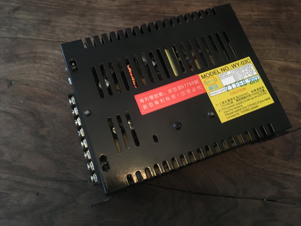
Next up i've managed to source (thanks to Craig for the molex part number) some correct molex connectors for the internal game wiring so i can build a cable for the missing +5 and +12v power supply and use a switched mode one running from 240v in.

IMG_9931.jpg


This is the switch mode psu i'm going to use for now. My plan is to source an original supply eventually but hoping this will work ok for now and is of reasonable quality. This can be run from 240v in so it will keep the load down on the internal 100v output transformer, so there are benefits here, but its not official or factory by any stretch!

IMG_9933.jpg


IMG_9934.jpg


PSU mains input cable using factory molex connectors

IMG_9935.jpg


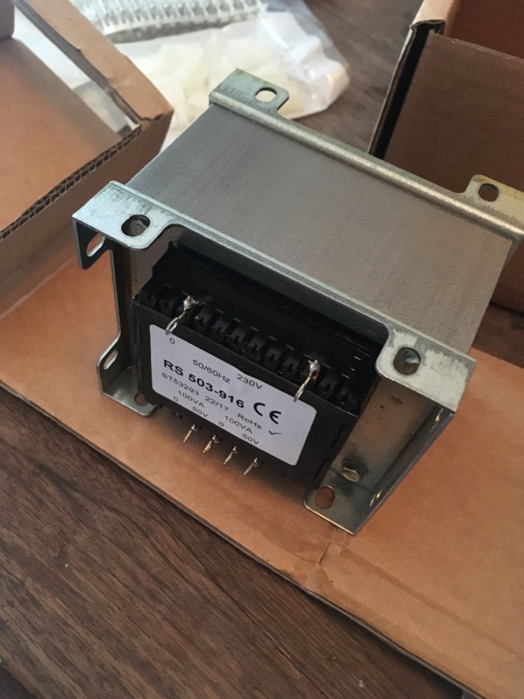
Here is the isolating transformer i have sourced that is 230v in and 100v output. (2 50v taps that can be connected in series) The spec is 200VA total so should be more than adequate for running the monitor and uv tube. If and when i get an original 5v/12v power supply then i may need to look at this again as the load may need to 300-320VA max for that.

IMG_9932.jpg
 

myPinballs

Active member
Feedback
16 (100%)
Credits
663CR
Whilst having a break earlier from all this electronic ness of the input stuff i snapped some pics of the underside of the control panel and buttons/wiring etc. Really nice to see all the metal uncorroded and still shiny

IMG_9913.jpg
IMG_9914.jpg
IMG_9915.jpg
IMG_9916.jpg


myPinballs2017-09-27 18:02:18
 

myPinballs

Active member
Feedback
16 (100%)
Credits
663CR
Some more updates.

I have my power supply stuff all sorted out now.

Updated Transformer Panel now has 240v in and 100v out

IMG_9977.jpg


Switched Mode Power supply wired up with plug and play looms

IMG_9980.jpg


Installed in cabinet

IMG_9990.jpg
IMG_9991.jpg


Gave it a quick test and the game pcb boots up ok. Also did a quick bench test on the board to check operation as i don't have the monitor (Sharp XM-2001N) working. Pcb all works good and is in very nice condition. (More pics of that later)

So next on the list is to fix up the Sharp Monitor. This is non working as the Horizontal Width coil heated up too much and fell out at some previous point in its life!! I am currently taking the monitor apart and cleaning up to assess the damage. I have the part that fell out so hoping that it can be reinstalled and the board damage repaired. The tube itself look in pretty good condition. Alittle minor screen burn from the r-type logo page but nothing too bad.

myPinballs2017-10-07 13:11:28
 

myPinballs

Active member
Feedback
16 (100%)
Credits
663CR
It Lives!

IMG_0095.jpg
IMG_0097.jpg
IMG_0102.jpg
IMG_0103.jpg
IMG_0104.jpg


The monitor needed to have its horizontal width coil reinserted (after it had fallen out of the board) plus i had to change a resistor that was burned up that fits in parallel to this coil. Also i needed to change the HOT which was shorted and of course replace a few fuses. And bingo.

Will do a cap change on it to and adjust the settings etc, but now just want to have a good blast on it for awhile!!

Monitor cleaned up pic.

IMG_0063.jpg


New Hot

IMG_0093.jpg


Width Coil Repair. The width coil casing had been damaged by the previous issue, but the coil istelf was intact and still ok. I straightened out the pcb lugs and repaired the pcb traces underneath and changed the burnt up resistor with a 'flame proof' modern version.

IMG_0059.jpg
 

sosfx

Active member
Credits
74CR
nice! its looking real good!

I know that you are looking to do a whole restore on the cab but the marquee is in keeping with the cabs age, I know its a bit yellow but personally I dont think its that bad.

good job and good luck with the rest
smiley1.gif
 

myPinballs

Active member
Feedback
16 (100%)
Credits
663CR
Another quick update.

After a lot of searching about and head scratching i managed to locate a source of marquee uv tubes that fit in nicely. As i've now got 100vac in side the cab again i connected up the original strip light assembly and hey presto all sorted. Glad that the ballast and starter were still ok on it!

IMG_0139.jpg
 

jase38

Active member
Feedback
45 (100%)
Credits
109CR
Looks great, awesome work. :)

Where did you get hold of the marquee tubes if you don't mind doing me asking?

I need one for my Donkey Kong.
 
Top