Sega G-LOC Air Battle Deluxe restoration project

Mariobros3

User
Credits
124CR
Thanks Bods! 🙂 Yes, there’s still plenty to do before I get to the sound!

The boots on mine are badly deteriorated and bunched up at the bottom of the rear posts. I still need to establish exactly what they should look like when intact, so I wouldn’t use mine as a reference! If anyone has a close-up of a good original pair, I’d be very interested to see it.

There’s certainly a lot of machinery hiding under the seat! For now, I’m taking it one step at a time, documenting everything as I dismantle it. Seeing it moving again is something to look forward to 🙂
 

Mariobros3

User
Credits
124CR
;)

Time for an update! Quite a bit has happened since removing the rear seat shells :)

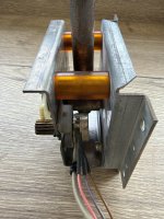
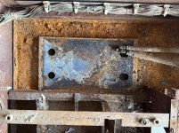
I’ve been working on the throttle assembly, including rust removal on the GLC-2103 — BASE BRKT B. I used HG rust remover diluted with water for this. The surface looks much better, although some pitting remains. The GLC-2108 torsion spring is missing, so I’m still looking for one.

IMG_6739.jpeg

IMG_6833.jpeg

I also removed all four protective rod boots to inspect them properly: two circular GLC-3017 — ROD BOOT and two rectangular GLC-3022 — ROD BOOT UPPER.

Unfortunately, all four are split and unusable as they stand. Both GLC-0016 retaining frames are broken too; I’ve glued one back together for now. The metal GLC-3023 upper holders have been cleaned, and I’ve documented the separate guides, plates and fixings to help work out what can be reused or reproduced.

IMG_6854.jpeg

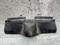
More recently, I removed the three skirts beneath the front section of the cockpit:

  • Two GLC-1040 — SKIRT SIDE, held by GLC-1038 — PROTECTOR SIDE strips.
  • One GLC-1039 — SKIRT FRONT, held by GLC-1037 — PROTECTOR FRONT strips.
Each skirt uses two retaining strips and four screws, specified in the manual as 008-0430 tamper-proof M4 × 30.

IMG_6879.jpeg

The front skirt has tears around its raised centre section. The side skirts look more complete, but still need cleaning before I can properly assess their condition.

IMG_6888.jpeg

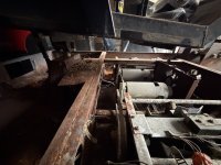
Removing them gives a much clearer view of the mechanism, wiring and underside of the cockpit. There’s plenty of dirt and debris to clear away, along with substantial corrosion on the exposed steelwork.

IMG_6895.jpeg

Still working through the dismantling, inspection and documentation stage. Every part removed helps me understand the cabinet a little better—and adds something else to the cleaning list :)

As usual, there are more photos and a detailed account of each step, including part numbers, in my restoration thread on Gamoover.

Thanks for following along :)
 

Mariobros3

User
Credits
124CR
;)

Time for another update! With the three skirts removed, I’ve carried on stripping down the cockpit.

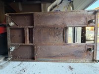
Next came the wooden seat base, « GLC-1012 — SEAT BASE », followed by the floor panel and the metal covers protecting the wiring. Removing these exposed the loom running underneath.

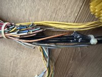
The same loom also branches off towards the monitor and joystick, as well as the throttle, fluorescent light and rear speakers. I photographed its routing and fixing points before removing it to help with reassembly later.

IMG_6944.jpeg

With the loom out, I found a badly damaged section of insulation on one of the blue wires, with the conductor exposed in several places. Another repair to add to the list before it goes back in.

IMG_6953.jpeg

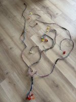
Here’s the complete loom after cleaning, laid out so its different branches are easier to follow.

IMG_6954.jpeg

Next was the monitor and joystick support, including the « GLC-1009 — ASSY MONITOR BASE » and metal « GLC-1017 — PANEL SUPPORT ». Four M6 × 25 hex-head bolts, accessible from underneath, secure it to the cockpit. Once these were removed, the whole assembly could be lifted off.

IMG_6968.jpeg

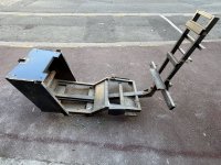
With the cockpit stripped back to its frame, I could finally separate it from the base. This involved removing the front pivot shaft and disconnecting the two rear linkages.

Here’s the cockpit structure on its own—a fairly big milestone in the dismantling!

IMG_6983.jpeg

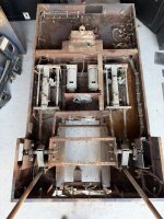
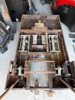
And here’s what was underneath. The motors, drive mechanisms and remaining wiring are now accessible for the next stage.

There’s substantial corrosion on the base, along with plenty of dirt and debris. At least I can now get a proper look at everything.

IMG_6982.jpeg

The cabinet is getting emptier, while the pile of parts waiting for attention keeps growing

As usual, there are more photos and a detailed account of each step, including part numbers, in my restoration thread on Gamoover.

Thanks for following along :)
 

Attachments

  • IMG_6981.jpeg
    IMG_6981.jpeg
    128.4 KB · Views: 2
Last edited:

Mariobros3

User
Credits
124CR
;)

Time for another update! With the cockpit separated from the base, I’ve been carrying on with the dismantling.

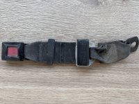
First, a small detour to look at the original seat belt, listed as « RH-1104 — SEAT BELT » in the Sega manual. After cleaning, I could read its markings: « NIPPON SEIKO K.K. — MADE IN JAPAN — MOD. NSB-1013 — RB02 ».

IMG_6988.jpeg

IMG_6999 2.jpeg

The male tongue is missing. I previously replaced the belt on my After Burner Deluxe, so I’ll check whether the tongue from its old belt fits the G-LOC buckle. Compatibility is still unconfirmed, but I’d like to preserve as many original parts as possible.

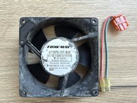
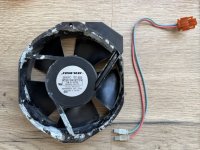
Back to the base, I removed the two cooling fans. The smaller one ventilates the game PCB and is a « FLOWMAX — 4715PS-10T-B30 ». The larger one is a « FLOWMAX — 5915PC-10T-B30 ». Both are rated for 100 V AC.

Here they are after cleaning.

IMG_7064.jpeg

IMG_7068.jpeg

The larger fan was already disconnected when I received the cabinet, and its blades are completely seized. That may explain why it had been unplugged. I’ll need to find a replacement; depending on prices and availability, I may replace both. The smaller fan still needs testing.

Next came the two motor assemblies, listed as « YZ-3203 — ASSY MOTOR ». Each has two cables connecting it to the loom and drives its mechanism through a V-belt.

IMG_7037.jpeg

Both motors are now out, still attached to their brackets and pulleys. One retains its « SEGA — MODEL 16611 » label. They turn by hand, but I’ll inspect them properly, including the brushes, when I dismantle them for cleaning.

IMG_7042.jpeg

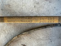
The belts are marked « BANDO POWER ACE — 3V-280 », corresponding to Sega part « 350-5198 — V BELT ».

IMG_7045.jpeg

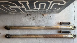
I then removed the two connecting rods and the potentiometer assemblies that provide position feedback. This cleared the way to remove both « GLC-3050 — ASSY MECHANISM » assemblies, each containing a ball screw and two limit switches.

IMG_7054.jpeg

IMG_7083.jpeg

Removing them revealed quite a difference between the two mounting areas. One still has a fair amount of paint underneath; the other is much more heavily corroded.

IMG_7087.jpeg
 

Mariobros3

User
Credits
124CR
Continuing with the base…

With the mechanisms removed, I could finally take out the remaining base looms. Cleaning and electrical checks will follow before reassembly.

IMG_7104.jpeg

The base is now considerably lighter, so I tipped it onto its side to inspect the underside, castors and adjustable feet. There’s more corrosion to deal with underneath…

IMG_7106.jpeg

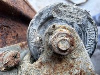
The four castors carry « NANSHIN » and « 50 × 28 » markings. Their brackets have also suffered from corrosion.

IMG_7107.jpeg

I also managed to unscrew one adjustable foot, with some difficulty and help from WD-40, so I can examine it more closely and identify its specifications.

IMG_7118.jpeg

The pile of removed parts keeps growing! There’s still plenty of cleaning and inspection ahead, but access to the base is much better now.

As usual, the full photo-by-photo account and detailed part references are in my restoration thread on Gamoover.

Thanks for following along :)
 

Mariobros3

User
Credits
124CR
;)

Time for another update!

With the remaining base looms removed, I’ve started cleaning them and checking their condition. Several cut wires have turned up, so there will be some repair work before reassembly.

Some of the matching wires are on another section of the loom, while others still need tracing. For now, I’m documenting everything before deciding what needs replacing.

IMG_7134.jpeg

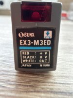
Next came the optical safety sensors around the base. I’ve removed and cleaned the first one, which is labelled « SUNX — EX3-M3ED ». Sega lists it as « 370-5019 — BEAM SENSOR ».

The system uses three emitter/receiver pairs to detect an obstruction around the moving cockpit. Cleaning is done on this first sensor, but its operation still needs checking.

IMG_7148.jpeg

I also removed the last two fans, mounted together on the left-hand cover. The screws were badly rusted, and some were quite difficult to remove.

Both fans are « FLOWMAX — 4715PS-10T-B30 », rated at 100 V AC, 50/60 Hz and 14/13 W—the same model as the PCB cooling fan removed earlier.

One detail I haven’t found in the manual’s exploded view is this arrangement of two fans with their shared cover and protective grilles.

IMG_7157.jpeg

The two remaining crank assemblies, « GLC-3130 — ASSY CRANK », and their long connecting rods are now out as well. After that, I removed the remaining loom clips from the chassis.

The base is now almost completely stripped. With everything out of the way, the extent of the corrosion is much easier to see.

IMG_7175.jpeg

I’ve temporarily put the covers back in place for an overall view. The next decision is how to tackle stripping and repainting the chassis and panels.

I’ll ask the professional who previously worked on my Galaxy Force base for a quote, then decide whether to have the work done or tackle it myself.

As usual, the full photo-by-photo account and detailed part references are in my restoration thread on Gamoover.


Thanks for following along :)
 

Mariobros3

User
Credits
124CR
Thanks, Bods! I didn’t know the Rail Chase seat also had beam sensors around it and an emergency stop button on the control panel.

Rail Chase is another cabinet I’d love to own someday :)
 

iamjimmi

Active member
vacBacker
Feedback
8 (100%)
Credits
494CR
"Both motors are now out, still attached to their brackets and pulleys. One retains its « SEGA — MODEL 16611 » label. They turn by hand, but I’ll inspect them properly, including the brushes, when I dismantle them for cleaning."

In case it is relevant, read this thread before dismantling the motors....


The relevant posts are about the use of a keeper....
 

Mariobros3

User
Credits
124CR
Thanks, iamjimmi! I wasn’t aware of this issue, so I really appreciate the warning and the link.

I’ll read through the thread before opening the motors and check whether the same precautions apply to the G-LOC ones. I’m trying to preserve them, so this is exactly the kind of advice that could save me from an expensive mistake :)
 

iamjimmi

Active member
vacBacker
Feedback
8 (100%)
Credits
494CR
Thanks, iamjimmi! I wasn’t aware of this issue, so I really appreciate the warning and the link.

I’ll read through the thread before opening the motors and check whether the same precautions apply to the G-LOC ones. I’m trying to preserve them, so this is exactly the kind of advice that could save me from an expensive mistake :)

Loving the thread... you are are doing an amazing job....
 

Mariobros3

User
Credits
124CR
Thank you! It’s encouraging to know you’re enjoying the thread :) There’s still a lot to do, and advice like yours really helps me preserve as much of the original hardware as possible.
 
Top